display panel

A display panel and substrate technology, applied to static indicators, instruments, etc., can solve problems such as insufficient output capacity and abnormal display of the display, and achieve the effect of high driving ability

Inactive Publication Date: 2017-12-05
CHUNGHWA PICTURE TUBES LTD
View PDF5 Cites 0 Cited by
  • Summary
  • Abstract
  • Description
  • Claims
  • Application Information

AI Technical Summary

Problems solved by technology

However, limited by the manufacturing process, thin film transistors may have insufficient output capability in a low-temperature environment, which may cause the display to fail to display normally when it is turned on.

Method used


Image

  • display panel
  • display panel
  • display panel

Examples


Embodiment Construction

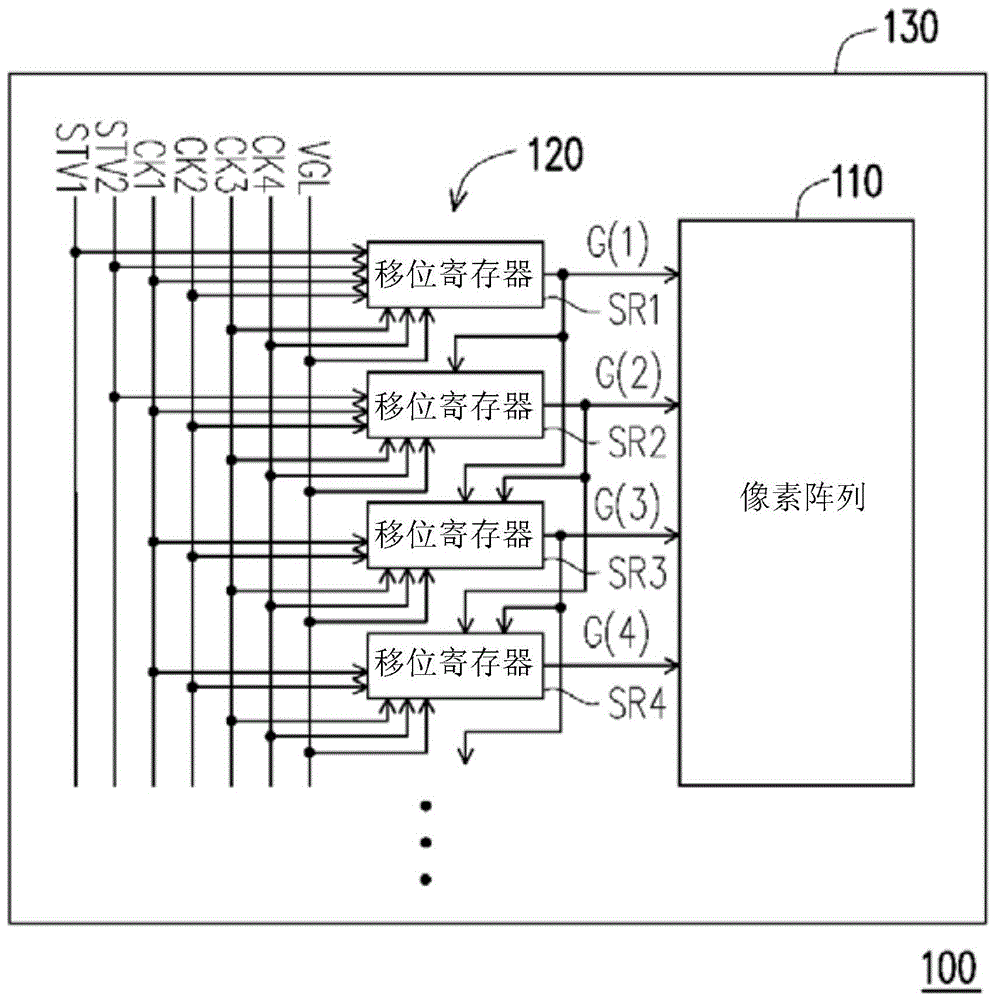
[0034] figure 1 It is a system diagram of a display panel according to an embodiment of the present invention. Please refer to figure 1 , in this embodiment, the display panel 100 includes a pixel array 110, a gate driving circuit 120 and a substrate 130, wherein the function of the gate driving circuit 120 is similar to a gate driver, that is, the gate driving circuit 120 will output a single pulse Scanning signals (such as G(1)˜G(4)) are sent to the pixel array 110 to drive the pixels (not shown) of the pixel array 110 .

[0035] In this embodiment, the gate driving circuit 120 is disposed on the substrate 130 and is located on the left side of the pixel array 110 . In other embodiments, the gate driving circuit 120 can be disposed on other sides of the pixel array 110 , such as the right side, the lower side or the upper side. Moreover, the pixel array 110 on the substrate 130 can be regarded as a display area of ​​the display panel 100 , and the disposition area of ​​th...


PUM


Abstract

The invention provides a display panel, which includes a pixel array and a plurality of shift registers. The shift register is used for sequentially outputting a plurality of scanning signals to drive the pixel array. Each shift register includes a first charging unit, a second charging unit, a driving unit and a discharging unit. The first charging unit is used for charging a reference voltage during a first period. The second charging unit is used for charging the reference voltage during a second period. The driving unit outputs a first clock signal as a corresponding scanning signal and boosts the reference voltage in a third period according to the reference voltage. The discharge unit decides whether to discharge the reference voltage and the corresponding scanning signal according to the reference voltage.

Description

technical field [0001] The present invention relates to a display panel, and in particular to a display panel with a shift register. Background technique [0002] In recent years, with the vigorous development of semiconductor technology, portable electronic products and flat panel display products are also emerging. Among many types of flat panel displays, Liquid Crystal Display (LCD) has become the mainstream of display products due to its advantages of low voltage operation, no radiation scattering, light weight and small size. [0003] In order to lower the production cost of liquid crystal displays, some manufacturers have proposed to use thin film transistors (thin film transistor, TFT) directly on the glass substrate to make a multi-level shift register (shift register), so as to replace the existing conventional The gate driving chip (Gate driving chip), in order to reduce the production cost of the liquid crystal display. However, due to the influence of the manuf...

Claims


Application Information

Patent Timeline
Patent Type & Authority Patents(China)
IPC IPC(8): G09G3/36
Inventor 郭智宇
Owner CHUNGHWA PICTURE TUBES LTD
Why Eureka
Try Eureka