Vacuum lock system and substrate processing method

A technology of vacuum treatment and vacuum lock, applied in electrical components, semiconductor/solid-state device manufacturing, circuits, etc., can solve problems such as robot motion burden, and achieve the effect of reducing the burden

Active Publication Date: 2016-05-11
ADVANCED MICRO FAB EQUIP INC CHINA
View PDF3 Cites 14 Cited by
  • Summary
  • Abstract
  • Description
  • Claims
  • Application Information

AI Technical Summary

Problems solved by technology

[0004] Although this kind of load lock device has further improved its utilization efficiency, however, the manipulator of the robot has to carry out the substrate transfer to the load lock device and the plasma processing chamber of different heights, which will undoubtedly cause a burden on the movement of the robot, so it is necessary to Improve the load-locking device to simplify the structure and operation of the load-locking device and the robot

Method used


Image

  • Vacuum lock system and substrate processing method
  • Vacuum lock system and substrate processing method
  • Vacuum lock system and substrate processing method

Examples


Embodiment Construction

[0036] In order to make the content of the present invention clearer and easier to understand, the content of the present invention will be further described below in conjunction with the accompanying drawings. Of course, the present invention is not limited to this specific embodiment, and general replacements known to those skilled in the art are also covered within the protection scope of the present invention.

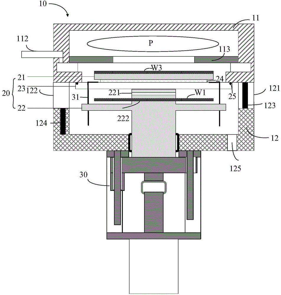
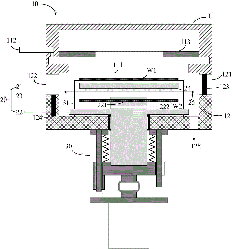
[0037] figure 1 with figure 2is a cross-sectional view of a vacuum lock system according to an embodiment of the present invention. The vacuum lock system has a chamber body 10 , a substrate support assembly 20 and a lifting mechanism 30 . The chamber main body 10 includes a first chamber 11 and a second chamber 12, and the first chamber 11 and the second chamber 12 are vertically stacked together. Wherein, the first chamber 11 is used for performing plasma treatment on the substrate placed therein, for example, it may be a photoresist-removing plasma treatment...


PUM


Abstract

The invention discloses a vacuum lock system for transmitting substrates. The vacuum lock system comprises a cavity body, a substrate support assembly and an elevating mechanism; the cavity body comprises a first cavity and a second cavity, two openings which can be connected to the atmosphere environment or the vacuum processing environment are formed in the sidewall of the second cavity, and the first cavity carries out plasma processing on the substrate therein; the substrate support assembly is arranged in the cavity body in a liftable manner, and comprises a partition plate, a first support member and a second support member, the partition plate, the first support member and the second support member are stacked vertically, and the first and second support members bear the substrate; the elevating mechanism drives the substrate support assembly to move between a first position and a second position. In the first position, the partition plate seals up a bottom opening of the first cavity, the first support member is arranged in the first cavity, and the second support member corresponds to the two openings in the sidewall of the second cavity. In the second position, the first support member corresponds to the two openings. According to the invention, the substrate processing efficiency can be improved, and the movement load of a transmission robot is alleviated.

Description

technical field [0001] The invention relates to semiconductor processing equipment and methods, in particular to a vacuum lock system and a substrate processing method. Background technique [0002] In the manufacturing process of semiconductor devices, various vacuum processing chambers are usually used to perform specific treatments such as thin film deposition, etching, oxidation or nitridation, heat treatment, etc. on the semiconductor wafer as the substrate to be processed in a vacuum environment. On the other hand, transfer of semiconductor wafers from the outside to such a vacuum processing chamber is generally carried out by including a load lock device for switching the internal pressure between an atmospheric pressure state and a vacuum state. Generally, the load lock device is disposed between the vacuum transfer chamber and the outside of the atmospheric environment, such as a wafer cassette or factory interface. The vacuum transfer chamber is connected with eac...

Claims


Application Information

Patent Timeline
Patent Type & Authority Applications(China)
IPC IPC(8): H01L21/67
Inventor 雷仲礼刘身健
Owner ADVANCED MICRO FAB EQUIP INC CHINA
Why Eureka
Try Eureka