Frequency selection surface structure based on stereo structure

A frequency selective surface, three-dimensional structure technology, applied in electrical components, antennas, etc., can solve problems such as few controllable parameters, small slope of frequency response curve, and poor miniaturization

Active Publication Date: 2016-05-11
HARBIN INST OF TECH
View PDF5 Cites 18 Cited by
  • Summary
  • Abstract
  • Description
  • Claims
  • Application Information

AI Technical Summary

Problems solved by technology

[0006] The present invention aims to solve the problems that the existing frequency selective surface with simple structure has relatively few controllable parameters, t

Method used


Image

  • Frequency selection surface structure based on stereo structure
  • Frequency selection surface structure based on stereo structure
  • Frequency selection surface structure based on stereo structure

Examples


specific Embodiment approach 1

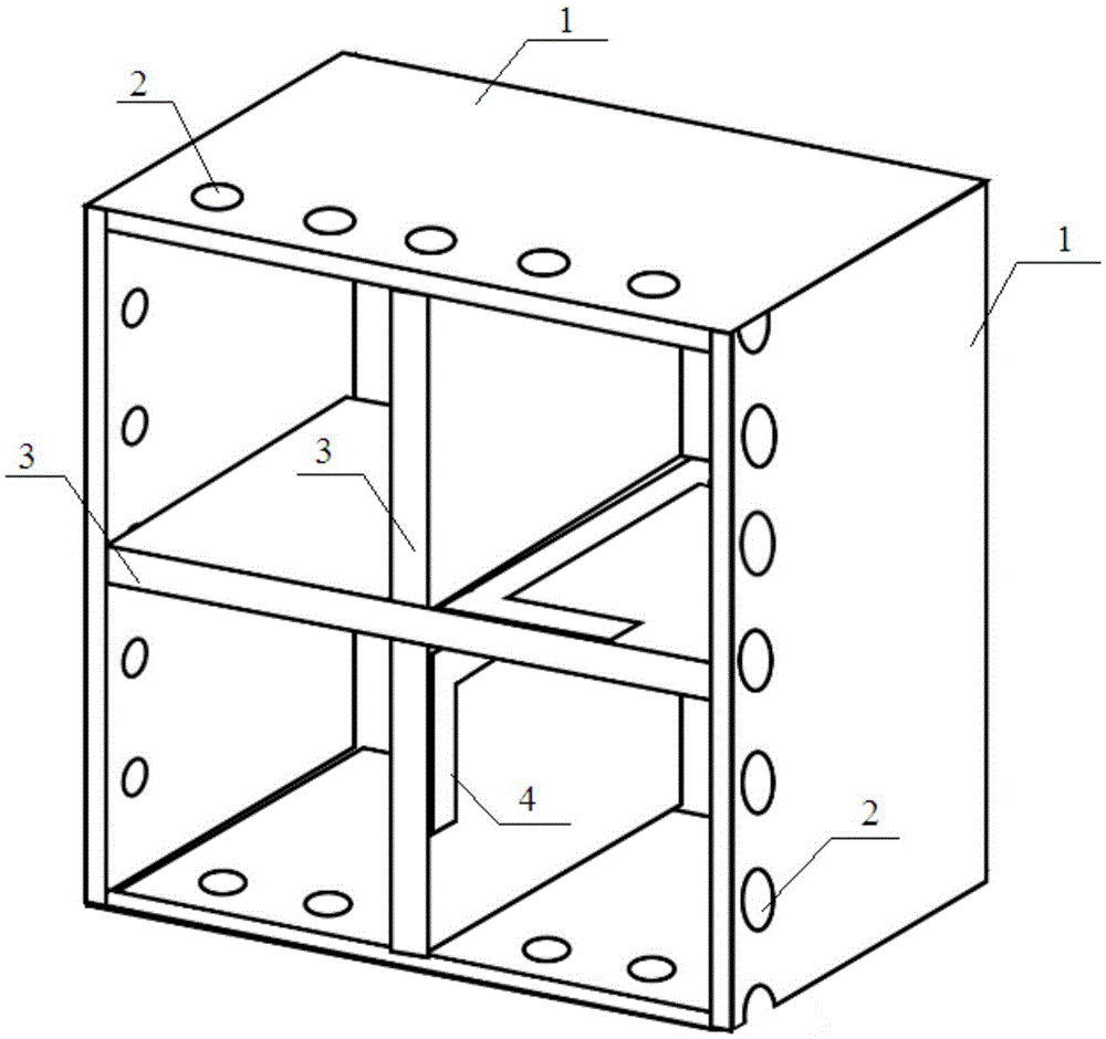
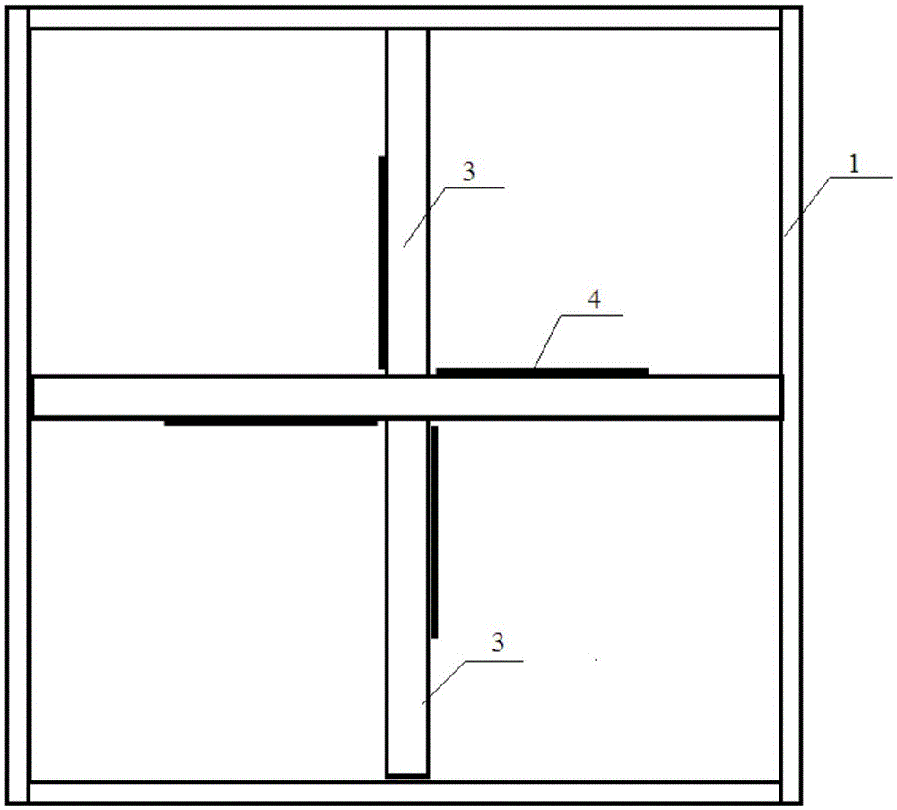
[0018] Specific implementation mode 1. Combination Figure 1 to Figure 5 Describe this embodiment, the frequency selective surface structure based on the three-dimensional structure described in this embodiment includes n frequency selective unit structures, and the n frequency selective unit structures are loaded in an array, and each frequency selective unit structure includes four No. 1 dielectric board 1, two No. 2 dielectric boards 3 and metal film strips 4; n is an integer greater than 1;

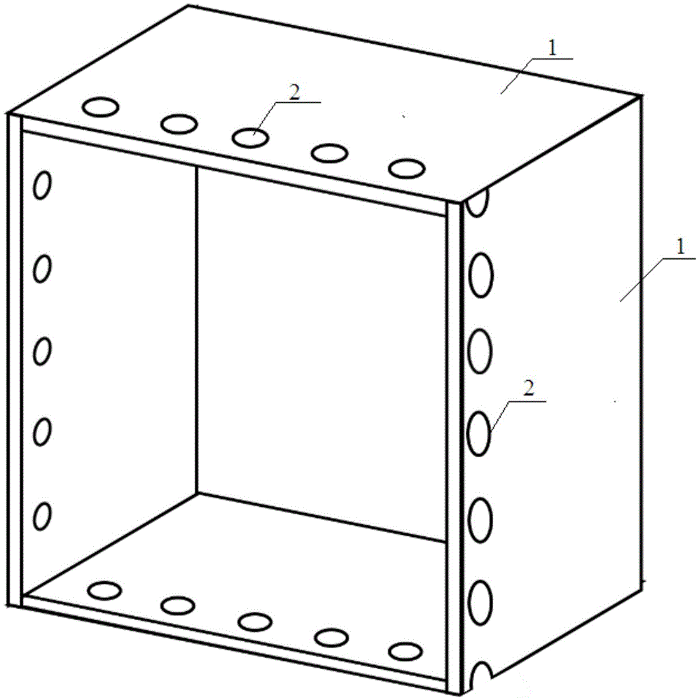
[0019] Four No. 1 dielectric boards 1 are vertically spliced ​​to form a rectangular frame. The inner wall of the rectangular frame is coated with a metal film layer. The No. 1 dielectric board 1 is provided with circular through holes, and the circular through holes are arranged at equal intervals near the incident side of electromagnetic waves. , the circular through holes on the two dielectric plates 1 opposite to the rectangular frames are arranged oppositely, and the inner side o...

specific Embodiment approach 2

[0021] Embodiment 2. This embodiment is a further description of the frequency selective surface structure based on the three-dimensional structure described in Embodiment 1. The length of the rectangular frame formed by the vertical splicing of No. 1 dielectric plate 1 is 15.6 mm and the width is 15.6 mm. , The height is 10mm.

specific Embodiment approach 3

[0022] Embodiment 3. This embodiment is a further description of the three-dimensional structure-based frequency selective surface structure described in Embodiment 1. The dielectric constant of No. 1 dielectric plate 1 is 4.3.


PUM

PropertyMeasurementUnit
Thicknessaaaaaaaaaa
Lengthaaaaaaaaaa
Widthaaaaaaaaaa

Abstract

The invention provides a frequency selection surface structure based on a stereo structure, relates to the frequency selection surface structure and solves the problems that an existing frequency selection surface of a simple structure has fewer controllable parameters and is small in gradient of a frequency response curve, poor in polarization stability and poor in miniaturization in practical application. According to the invention, four No.1 medium plates are perpendicularly spliced to form a rectangular frame, a metal film layer is coated on the inner side wall of the rectangular frame, circular through holes are formed in the No.1 medium plates, and the a metal film layer is coated on the inner side of each circular through hole; and two No.2 medium plates are respectively arranged in the rectangular frame, one pair of opposite edges of each No.2 medium plate is fixedly connected with the inner side wall of the rectangular frame, the two No.2 medium plates are perpendicularly connected along a center line to form a cross structure, metal film strips are respectively arranged on the lower surface of a left arm, the upper surface of a right arm, the left side surface of an upper arm and the right side surface of the lower arm of the cross resonance structure. The frequency selection surface structure is applicable to manufacturing and usage of an antenna cover.

Description

technical field [0001] The invention relates to a frequency selective surface structure. Background technique [0002] Frequency Selective Surface (FSS), referred to as FSS, is a single-layer or multi-layer quasi-planar structure composed of a large number of passive resonant units arranged in two-dimensional periodicity on the dielectric layer. The concept of frequency selective surface originated from the research of grating, which was first discovered and proposed by American physicist David Rittenhouse; after years of research and development, frequency selective surface has been widely used in various fields from microwave band to light wave band middle. [0003] In engineering, frequency selective surfaces are widely used, covering many aspects of the electromagnetic field: In the microwave band, frequency selective surfaces are often used as sub-reflectors of reflector antennas to improve the utilization efficiency of reflector antennas. In addition, FSS It is also ...

Claims


Application Information

Patent Timeline
IPC IPC(8): H01Q15/00
CPCH01Q15/0013
Inventor 杨国辉丁旭旻李德皋张狂
Owner HARBIN INST OF TECH
Why Eureka
Try Eureka