
Power line laying detachable type wiring device

A cable routing device, split-type technology, applied in the field of power line laying detachable routing device, can solve the problems of difficulty, small gaps in power cable layout, large construction volume, etc., to achieve strong site adaptability and construction Less work intensity, flexible and convenient to use

Inactive Publication Date: 2016-05-11
STATE GRID CORP OF CHINA +1
View PDF7 Cites 1 Cited by
  • Summary
  • Abstract
  • Description
  • Claims
  • Application Information

AI Technical Summary

Problems solved by technology

[0002] When supplying power in a small area, when wiring, it is often necessary to arrange power cables through cable trenches to realize the connection between power supply and electrical appliances, while traditional cable trenches are mostly excavated directly on the ground A certain degree of groove, and harden the interior by adopting concrete structure or brick-concrete structure, and set up brackets on the side wall of the cable trench to arrange the power cables. Although this structure can meet the needs of cable arrangement operations , but in actual use, it is also found that the bottom of the traditional cable trench is obviously lower than the ground level, so it is very easy to get damp or even water accumulation inside, and it is extremely difficult to clean the water accumulation inside, which leads to power lines The working environment of the cable is extremely harsh. At the same time, because it is excavated on the ground, the construction volume is huge, the labor intensity is also great, and it is easy to be restricted by the site, and the layout is often unreasonable. Small gaps or chaotic arrangement seriously affect the daily maintenance and replacement of power cables. Therefore, it is necessary to develop a new type of power cable arrangement technology to overcome the serious shortcomings of existing cable trenches.

Method used


Image

  • Power line laying detachable type wiring device
  • Power line laying detachable type wiring device
  • Power line laying detachable type wiring device

Examples


Embodiment Construction

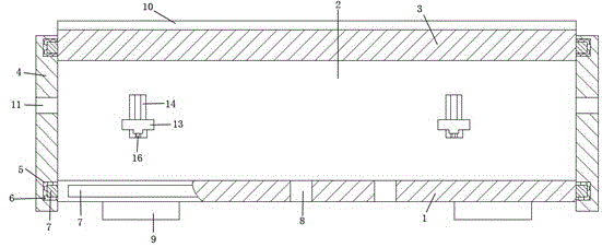
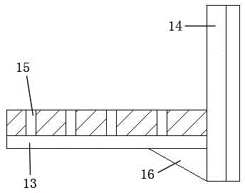
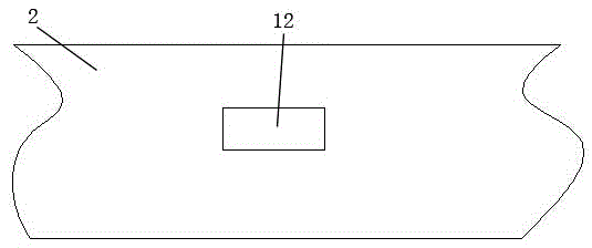
[0016] Such as figure 1 A power line laying detachable routing device is shown, its cross section is quadrilateral, and it is composed of a bottom plate 1, a side plate 2, a bracket, a cover plate 3 and a baffle plate 4, wherein the side plate 2 and the baffle plate 4 are both Two pieces, and the inner surface of the top and bottom of the connecting chute 5 is provided, and the sealing strip 6 is provided in the connecting chute 5, and the connecting slide bar 7 is provided on the edge of the bottom plate 1, and the connecting slide bar 7 is connected with the side plate 2 respectively. and the connecting chute 5 at the bottom of the baffle plate 4, the edge of the cover plate 3 is equipped with a connecting slide bar 7, and is respectively connected with the side plate 2 and the connecting chute 5 at the top of the baffle plate 4 through the connecting slide bar 7, and the bottom plate 1 is provided with a through hole 8. There are at least two supporting blocks 9 on the lowe...


PUM


Abstract

The invention discloses a power line laying detachable type wiring device, the cross section of which is in the shape of a quadrangle. The wiring device is constituted by a bottom plate, side plates, a supporting rack, a cover plate, and a baffle plate. The bottom plate is provided with transmitting holes, and the lower surface is provided with at least two supporting blocks, and the upper surface of the cover plate is uniformly provided with diversion grooves, and in addition, the baffle plate is additionally provided with wire penetrating holes. The outer surfaces of the side plates are respectively provided with at least one conveying grooves, and at least one supporting rack is disposed on the inner surfaces of the side plates, and each supporting rack is constituted by at least two supporting plates, each of which is constituted by a carrying plate and a connecting plate, and the carrying plate and the connecting plate are connected together by a reinforced rib plate. Compared to the conventional wire trench used for the wire arranging, the structure is simple, and the use is flexible and convenient, and the site adaptability is strong; the constriction costs are low, the construction strength is low, and the construction efficiency is high; the wire working environment can be greatly improved, and the daily inspection or the replacement of the power wire can be facilitated; and the wiring device is widely used for various power wire arranging occasions.

Description

technical field [0001] The invention relates to a detachable wiring device for laying power lines, which belongs to the technical field of power transmission equipment. Background technique [0002] When supplying power in a small area, when wiring, it is often necessary to arrange power cables through cable trenches to realize the connection between power supply and electrical appliances, while traditional cable trenches are mostly excavated directly on the ground A certain degree of groove, and harden the interior by adopting concrete structure or brick-concrete structure, and set up brackets on the side wall of the cable trench to arrange the power cables. Although this structure can meet the needs of cable arrangement operations , but in actual use, it is also found that the bottom of the traditional cable trench is obviously lower than the ground level, so it is very easy to get damp or even water accumulation inside, and it is extremely difficult to clean the water acc...

Claims


Application Information

Patent Timeline
Patent Type & Authority Applications(China)
IPC IPC(8): H02G9/02
Inventor 王秀荣安利孔令哲
Owner STATE GRID CORP OF CHINA
Learn More