

FPGA-based shakeless drive control system of stepping motor and control method based on same
A stepping motor, drive control technology, applied in the control system, motor generator control, electrical components, etc., can solve the problems of complex electrical system structure, poor drive timing accuracy, and insufficient external communication interfaces, so as to improve anti-interference performance, reduce the complexity of the electrical structure, and achieve the effect of jitter-free driving
- Summary
- Abstract
- Description
- Claims
- Application Information
AI Technical Summary
Problems solved by technology
Method used
Image

Examples
specific Embodiment approach 1
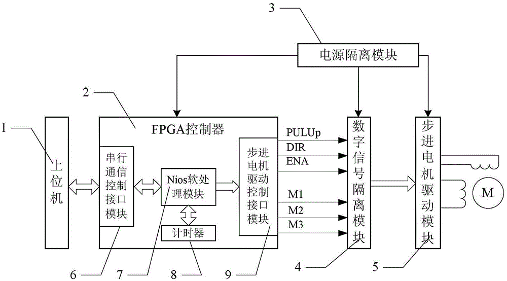
[0024] Specific implementation mode 1. Combination figure 1 Describe this specific embodiment, a kind of FPGA-based stepper motor vibration-free drive control system described in this specific embodiment includes host computer 1, FPGA controller 2, power supply isolation module 3, digital signal isolation module 4 and stepper motor The drive module 5, the host computer 1 realizes data interaction with the FPGA controller 2 through the serial communication bus, and the FPGA controller 2 outputs the pulse signal PULUp, the direction signal DIR, the enable signal ENA and the mode signal M1 to the digital signal isolation module 4 . The digital signal isolation module 4 is connected with the stepper motor driver module 5 .
specific Embodiment approach 2
[0025] Specific embodiment two, combine figure 1 Describe this specific embodiment, the difference between this specific embodiment and a kind of FPGA-based stepper motor jitter-free drive control system described in the specific embodiment one is that the FPGA controller 2 includes a serial communication control interface module 6, Nios soft processing module 7, stepping motor drive control interface module 8 and timer 9, described serial communication control interface module 6 realizes data interaction with upper computer 1 by serial communication bus, Nios soft processing module 7 passes Avalon bus respectively Realize data interaction with the serial communication control interface module 6, the stepper motor drive control interface module 8 and the timer 9.
specific Embodiment approach 3
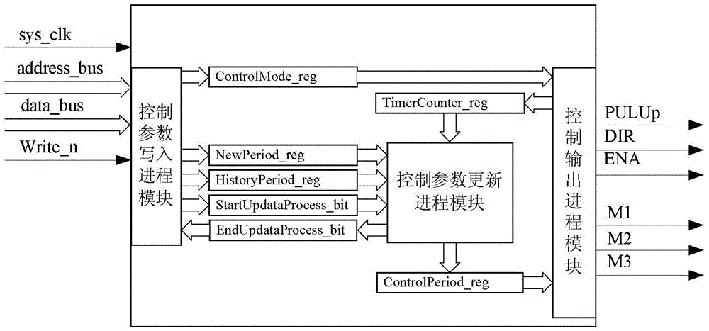
[0026] Specific embodiment three, combine figure 2 Describe this specific embodiment, the difference between this specific embodiment and a kind of FPGA-based jitter-free drive control system for stepping motors described in Embodiment 1 is that the stepping motor drive control interface module 8 includes:
[0027] A control parameter write process module for controlling the parameter write process;
[0028] A control parameter update process module for controlling the parameter update process;
[0029] A control output process module for controlling the output process;
[0030] The control mode register ControlMode_reg used to receive the signal sent by the control parameter writing process module and store the signal;
[0031] Driving timing counter TimerCounter_reg for driving timing counting;
[0032] The single-pulse control period parameter register ControlPeriod_reg used to receive the signal sent by the control parameter update process module and store the signal; ...
PUM
 Abstract
Description
Claims
Application Information