Supercharge Your Innovation With Domain-Expert AI Agents!

Automatic drilling and pressing pin equipment for plunger pump swash plate

A plunger pump and swash plate technology, applied in the field of automatic drilling and pinning equipment, can solve the problems of heavy labor and low production efficiency, and achieve the effects of reducing labor, improving production efficiency, and reducing electrical complexity

Active Publication Date: 2020-12-18
台州东科汽车空调压缩机有限公司
View PDF6 Cites 0 Cited by
  • Summary
  • Abstract
  • Description
  • Claims
  • Application Information

AI Technical Summary

Problems solved by technology

[0004] In order to meet the precision requirements of the pin hole 92, multiple drilling and reaming processes are required. In the prior art, the processing of the pin hole 92 and the press-fitting of the positioning pin 93 are respectively completed by multiple devices, involving frequent up and down Material and clamping process, manual labor is large and production efficiency is low

Method used


Image

  • Automatic drilling and pressing pin equipment for plunger pump swash plate
  • Automatic drilling and pressing pin equipment for plunger pump swash plate
  • Automatic drilling and pressing pin equipment for plunger pump swash plate

Examples


Embodiment 1

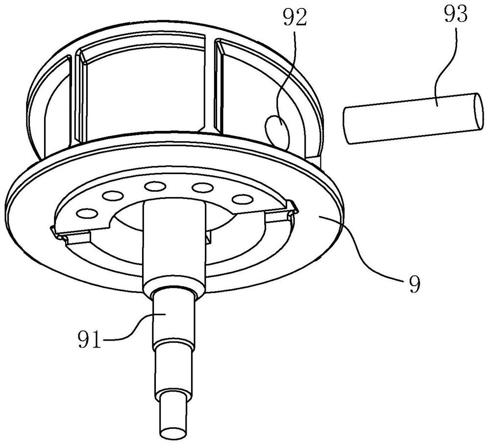
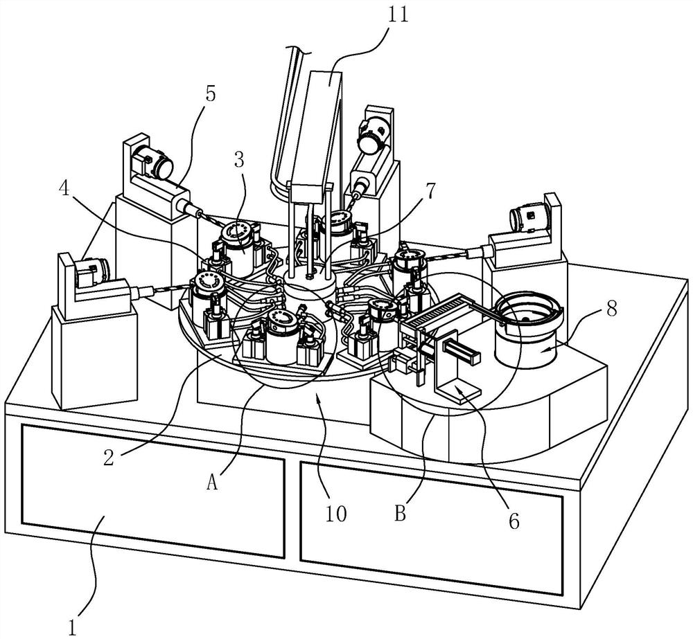
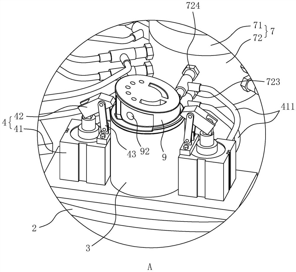
[0038] refer to figure 2 , is an automatic drilling and pinning device for a swash plate of a plunger pump disclosed in the present invention, comprising a frame 1, an indexing turntable 2 arranged on the top surface of the frame 1, and a plurality of Based on the clamping seats 3 for positioning the swash plate 9 and the clamps 4 for clamping the swash plate 9 , the clamping seats 3 are evenly distributed along the circumferential direction of the indexing turntable 2 . The top surface of the frame 1 outside the indexing turntable 2 is provided with a drilling rig 5 for drilling or reaming, a pinning machine 6 for pinning, and the circumferential distribution of the drilling rig 5 and pinning machine 6 on the indexing turntable 2 , Drilling machine 5, press pin machine 6 one by one are facing different holders 3, for processing the swash plate 9 on the holder 3. Frame 1 is provided with loading and unloading station 10, and there is clamp seat 3 correspondingly at 10 places...

Embodiment 2

[0049] An automatic drilling and pin pressing device for the swash plate 9 of a plunger pump, the difference between Embodiment 2 and Embodiment 1 is:

[0050] refer to Figure 7 , the top surface of the holder 3 is provided with a positioning projection 31 for being embedded in the hole on the end surface of the swash plate 9, the positioning projection 31 is slidably arranged in the holder 3 along the vertical direction, and the edge of the top surface of the positioning projection 31 is provided with an inverted horn. The piston rod of the clamping cylinder 41 is connected to the positioning projection 31 through a connecting rod 32 .

[0051] The height of the positioning bump 31 is set as follows: when the clamping cylinder 41 is in the shortened state, the height of the positioning bump 31 protruding from the top surface of the clamp seat 3 is 0.5~1.5mm, at this time, personnel can place the workpiece on the clamp seat 3 , The positioning bump 31 can play a preliminary...


PUM

PropertyMeasurementUnit
heightaaaaaaaaaa

Abstract

The invention discloses an automatic drilling and pin pressing device of a plunger pump swash plate, and relates to automatic equipment. According to the key points of the technical scheme, the automatic drilling and pin pressing device comprises a frame, clamping seats for positioning the swash plates, a clamp for clamping the swash plates, a drilling machine for drilling or reaming, a pin pressing machine for pressing pins, and a pin feeding mechanism for conveying the positioning pins to the pin pressing machine; an indexing rotating disc is arranged on the frame; the clamping seats are arranged on the indexing rotating disc; the drilling machine and the pin pressing machine are arranged on the frame outside the indexing rotating disc; and the drilling machine and the pin pressing machine are in one-to-one correspondence to different clamping bases and are used for machining the swash plates on the clamping seats. By using the automatic drilling and pin pressing device, a workpiecedoes not need to be subjected to frequent feeding, discharging and clamping procedures, so that the labor amount of workers is greatly reduced while the production efficiency is improved; air circuitdistribution is achieved without an electromagnetic reversing valve or control by a program, so that the electrical complexity is greatly reduced; and each clamping cylinder is capable of working automatically so as to achieve the loosening and clamping functions of the clamp.

Description

technical field [0001] The invention relates to an automatic device, in particular to an automatic drilling and pin pressing device for a swash plate of a plunger pump. Background technique [0002] The plunger pump includes a swash plate plunger pump. There are multiple cylinders and pistons arranged in the circumferential direction of the swash plate plunger pump. When the swash plate rotates one revolution, all the pistons complete a stroke of air intake and exhaust respectively. The swash plate plunger pump can compress gas and pump liquid. [0003] refer to figure 1 , is an existing swash plate assembly of a plunger pump, including a swash plate 9 and a rotating shaft 91 passing through the swash plate 9 . In order to limit the rotation of the swash plate 9 relative to the rotating shaft 91, the side wall of the swash plate 9 facing away from the rotating shaft 91 is provided with a pin hole 92, and a positioning pin 93 is pressed in the pin hole 92, and the positioni...

Claims


Application Information

Patent Timeline
Patent Type & Authority Patents(China)
IPC IPC(8): B23P23/02
CPCB23B41/00B23P19/001B23P19/027B23Q16/06
Inventor 游袁潘晓明潘国建
Owner 台州东科汽车空调压缩机有限公司
Features
  • R&D
  • Intellectual Property
  • Life Sciences
  • Materials
  • Tech Scout
  • Unparalleled Data Quality
  • Higher Quality Content
  • 60% Fewer Hallucinations
Learn More