Solar thermal collecting pipe and processing method thereof

A technology of solar collector tubes and core tubes, which is applied in the directions of solar collectors, solar thermal energy, solar collector components, etc., and can solve the problems of poor heat transfer efficiency and high cost in the field of medium-temperature solar thermal utilization that cannot be marketed quickly And other issues

Inactive Publication Date: 2016-05-18
NANJING CHENGYUAN SOLAR HEATING
View PDF9 Cites 15 Cited by
  • Summary
  • Abstract
  • Description
  • Claims
  • Application Information

AI Technical Summary

Problems solved by technology

[0007] However, at present, the core heat collecting tube elements used in the field of medium temperature solar heat utilization have not yet made a breakthrough, mainly manifested in 1. The miniaturization of high temperature power generation tubes is used for medium temperature solar heat collectors, but there is still no solution to the problem of complex structure and high cost. Problem; 2 adopt the external or built-in reflector structure of the conventional all-glass vacuum heat collecting tube. For example, the patent CN200910016660 adopts the external focusing structure of the all-glass vacuum heat collecting tube; the patent CN201210477159 adopts the internal focusing mode, but no matter which structure, the It is impossible to avoid the problem of poor heat transfer efficiency due to the all-glass structure of the inner tube
[0008] It can be seen that there is currently no medium-temperature solar collector tube that is completely suitable for the field of medium-temperature solar thermal utilization, which is also a fundamental factor that cannot be quickly marketed in the field of medium-temperature solar thermal utilization.

Method used


Image

  • Solar thermal collecting pipe and processing method thereof
  • Solar thermal collecting pipe and processing method thereof
  • Solar thermal collecting pipe and processing method thereof

Examples


Embodiment 1

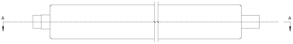
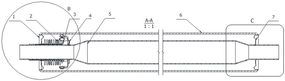
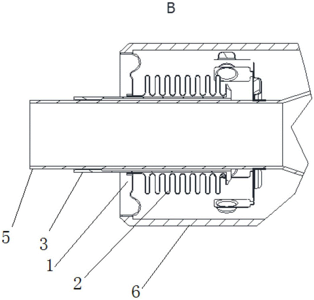
[0079] see Figure 1-Figure 6 , the solar heat collecting tube, comprising a straight-through metal inner tube 5, a cover glass tube 6, a left end cover 1 and a right end cover 7; a vacuum interlayer is formed between the straight-through metal inner tube 5 and the cover glass tube 6; With selective absorption coating; the straight-through metal inner tube 5 passes through the cover glass tube 6 and the two ends of the straight-through metal inner tube 5 extend out of the cover glass tube 6; the two ends of the straight-through metal inner tube 5 The diameter is smaller than the diameter of the middle part, forming the left end variable diameter section, the middle section and the right end variable diameter section; also including the bellows 2 and the connection between the left end variable diameter section and the cover glass tube 6 and located in the cover glass tube 6 Sleeve 3; the variable diameter section at the left end passes through the inner hole of the connecting ...

Embodiment 2

[0083] The right variable diameter section of this embodiment 2 adopts the same structure as the left variable diameter section, that is, the right connecting sleeve, the right bellows, and the metal end cap are used to replace the single metal end cap, that is, between the right variable diameter section and the cover glass tube 6 The right bellows and the right connecting sleeve are provided, and the right bellows and the right connecting sleeve are located in the cover glass tube 6; the reducing section at the right end passes through the inner hole of the right connecting sleeve and is sealed and connected with the inner wall of the right connecting sleeve by welding The right connecting sleeve passes through the right bellows and the left end of the right connecting sleeve is welded to the left end of the right bellows, the right end of the right connecting sleeve is connected to the inner peripheral surface of the right end of the right bellows, and the outer peripheral su...

Embodiment 3

[0085] On the basis of Embodiment 1 or 2, the solar heat collecting tube is equipped with an exhaust tail pipe opening on the side wall of the cover glass tube 6, and the similarities will not be described in detail.


PUM

PropertyMeasurementUnit
thicknessaaaaaaaaaa
diameteraaaaaaaaaa

Abstract

The invention discloses a solar thermal collecting pipe. A left end cap is formed by sequentially connecting an inner hole flange, a straight section, a circular-arc section, an outer circle and an outer circle flange from inside to outside. A connecting sleeve penetrates through a corrugated pipe and the right end of the connecting sleeve is welded to the right end of the corrugated pipe. The left end of the connecting sleeve is in seal connection with the inner circumferential face of the left end of the corrugated pipe. The outer circumferential face of the left end of the corrugated pipe is in seal connection with the inner hole flange of the left end cap. Transition glass is arranged on the circumference of the outer circle of the left end cap. The outer edge of the transition glass of the left end cap is connected with a cover glass pipe through fusion sealing. A right end cap and the left end cap are of the same structure. The right end cap is formed by sequentially connecting a right inner hole flange, a right straight section, a right circular-arc section, a right outer circle and a right outer circle flange from inside to outside. A right end diameter-changing section is in welded connection with the right inner hole flange. Right transition glass is arranged on the circumference of the right end cap. The outer edge of the right transition glass is connected with the cover glass pipe through fusion sealing. The invention further discloses a processing method of the solar thermal collecting pipe. The solar thermal collecting pipe is simple, reliable, convenient to produce and high in cost performance.

Description

technical field [0001] The invention relates to a heat collecting tube and a processing method thereof belonging to the field of solar heat utilization, in particular to a glass-metal fusion-sealed solar heat collecting tube with a straight-through necking structure and a processing method thereof. Background technique [0002] Solar thermal utilization is divided according to temperature, which can be divided into three fields at present: 40°C~80°C is the low temperature field, 80°C~250°C is the medium temperature field, and 250°C~800°C is the high temperature field. [0003] The heat utilization technology in the low temperature field is relatively mature at home and abroad, and mainly provides domestic water. Its products are flat plate or vacuum tube collectors. Due to the large heat loss, this type of collector can only be used at 40°C~80°C, and is mainly used in the field of low-temperature domestic hot water below 50°C. In particular, ordinary all-glass vacuum heat c...

Claims


Application Information

Patent Timeline
Patent Type & Authority Applications(China)
IPC IPC(8): F24J2/46
CPCF24S70/30F24S80/00F24S2025/6013F24S10/45F24S70/225F24S70/25Y02E10/44
Inventor 朱雷杨兵
Owner NANJING CHENGYUAN SOLAR HEATING
Why Eureka
Try Eureka