
Heat-Resistant Microporous Film And Battery Separator

一种电池、隔膜的技术,应用在耐热微孔膜领域,能够解决内部短路等问题,达到数量增加、维持耐热性的效果

Active Publication Date: 2016-05-18
MURATA MFG CO LTD
View PDF4 Cites 3 Cited by
  • Summary
  • Abstract
  • Description
  • Claims
  • Application Information

AI Technical Summary

Problems solved by technology

Shrinkage of the diaphragm causes secondary problems such as internal short circuits in some cases

Method used


Image

  • Heat-Resistant Microporous Film And Battery Separator
  • Heat-Resistant Microporous Film And Battery Separator
  • Heat-Resistant Microporous Film And Battery Separator

Examples


Embodiment 1

[0108] Polyvinylidene fluoride (PVdF) resin and N-methyl-2-pyrrolidone (NMP) each having a weight average molecular weight of 1,000,000 were mixed at a weight ratio of PVdF:NMP=10:90. Polyvinylidene fluoride was sufficiently dissolved in N-methyl-2-pyrrolidone, thereby preparing a polyvinylidene fluoride solution in which polyvinylidene fluoride was dissolved in an amount of 10% by weight.

[0109] A fine powder of alumina with an average particle size of 500 nm [Al 2 o 3 , Sumicorundum (registered trademark) AA-03, commercially available from Sumitomo Chemical Company, Limited] as an inorganic material was added to the polyvinylidene fluoride solution at 20 times the weight of polyvinylidene fluoride. The resultant was then stirred with a ball mill, thereby preparing a use slurry.

[0110] Next, the application slurry was applied to a substrate having a thickness of 12 μm as a polyethylene microporous membrane (commercially available from Tonen General Sekiyu K.K.) using a ...

Embodiment 2

[0116] The heat-resistant layers were individually formed on both faces of the substrate so that one heat-resistant layer had a thickness of 1.55 μm and the total heat-resistant layers had a thickness of 3.1 μm. A microporous membrane with a heat-resistant layer was produced in the same manner as employed in Example 1 except for such a process configuration.

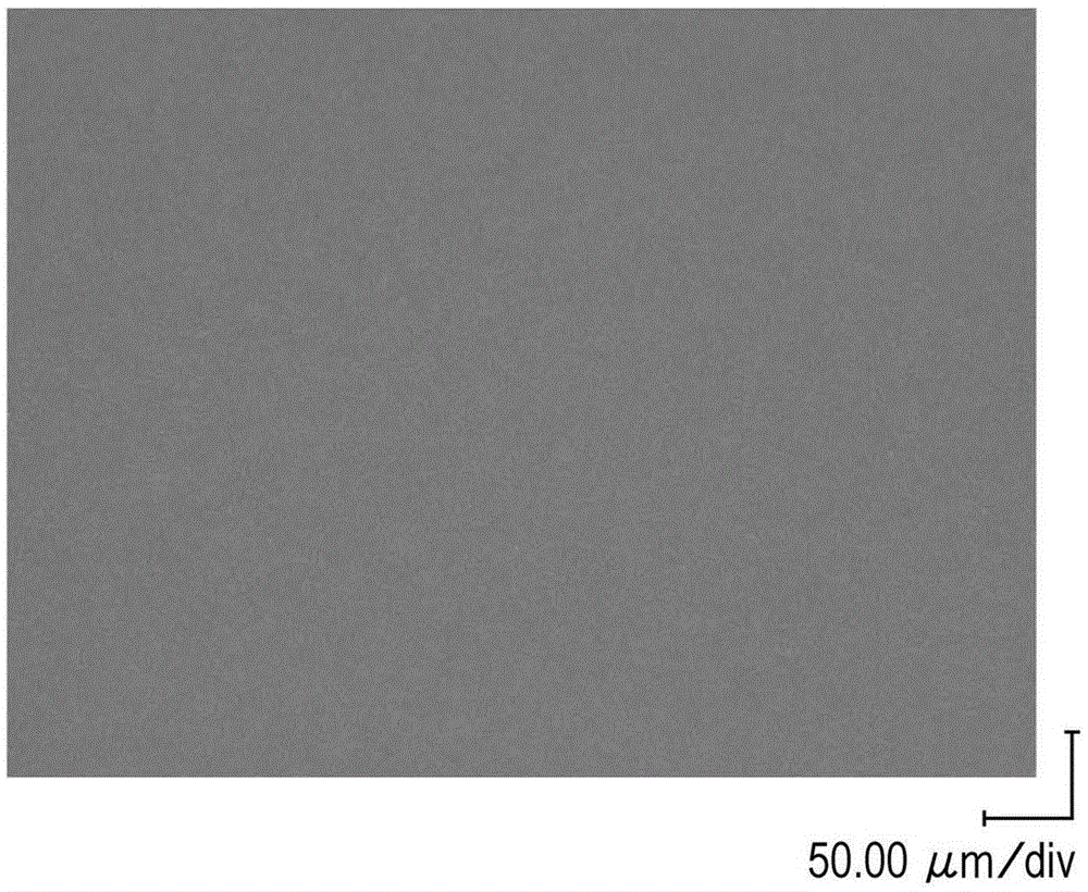
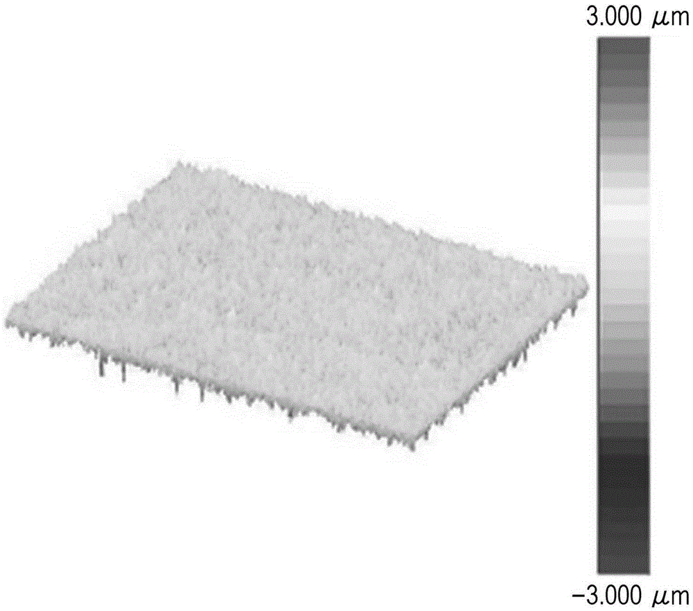
[0117] In the microporous membrane produced in this way, the total thickness of the heat-resistant layer was 6.2 times the average particle diameter of the heat-resistant particles contained in the heat-resistant layer. In addition, in the surface of the heat-resistant layer, it was found that the number of protrusions was 20.7 and the area was 46.1 μm 2 .

Embodiment 3

[0119] The heat-resistant layers were individually formed on both faces of the substrate so that the thickness of one heat-resistant layer was 2.75 μm and the total thickness of the heat-resistant layers was 5.5 μm. A microporous membrane with a heat-resistant layer was produced in the same manner as employed in Example 1 except for such a process configuration.

[0120] In the microporous membrane produced in this way, the total thickness of the heat-resistant layer was 11.0 times the average particle diameter of the heat-resistant particles contained in the heat-resistant layer. In addition, in the surface of the heat-resistant layer, it was found that the number of protrusions was 1.4 and the area was 1.0 μm 2 .


PUM

PropertyMeasurementUnit
particle diameteraaaaaaaaaa
porosityaaaaaaaaaa

Abstract

The invention relates to a heat-resistant microporous film and a battery separator. The heat-resistant microporous film and a battery separator are provided, which each include a substrate formed by using a porous film and include a heat-resistant layer formed on at least one surface of the substrate so as to contain a heat-resistant resin and heat-resistant particles, and in which a protrusion is formed on a surface of the heat-resistant layer in number not exceeding 60 per surface area of 0.0418 mm2 and has an area not exceeding 500 [mu]m2 per surface area of 0.0418 mm2 in a direction normal to a surface of the heat-resistant layer, the protrusion being formed as a result of aggregation of the heat-resistant particles and having a height of at least twice the average particle size of the heat-resistant particles with reference to the height average surface of the heat-resistant layer.

Description

[0001] This application is a divisional application of an invention patent application with an application date of November 10, 2011, an application number of 201110354115.7, and an invention title of "heat-resistant microporous membrane and battery separator". technical field [0002] The present invention relates to a heat-resistant microporous film (heat-resistant microporous film) having a heat-resistant insulating layer (heat-resistant insulating layer), and more particularly relates to a heat-resistant microporous film each having a substrate (substrate) and a heat-resistant layer (heat-resistant layer). A thermal microporous film and a battery separator, the substrate is made by using a polyolefin resin, and the heat-resistant layer has a structure in which inorganic particles are contained in the heat-resistant resin. Background technique [0003] In recent years, portable electronic information devices such as mobile phones, camcorders, and notebook computers have be...

Claims


Application Information

Patent Timeline
Patent Type & Authority Applications(China)
IPC IPC(8): H01M2/14H01M2/16H01M2/18H01M10/42H01M50/403H01M50/451H01M50/457H01M50/463H01M50/489H01M50/491
CPCH01M10/4235H01M10/052H01M50/446H01M50/403H01M50/463H01M50/451H01M50/491H01M50/489H01M50/457Y10T428/24372Y02E60/10H01M10/0525H01M2220/30
Inventor 柿部亚希子李成吉冈本和广
Owner MURATA MFG CO LTD
Learn More