Mold for manufacturing turbocharger

A cooling technology for molds and molds, which is applied in the manufacture of tools, casting molding equipment, casting molds, etc., can solve the problems of difficult recovery of cooling water, increase of production costs, slow cooling rate, etc., to avoid flash burrs and air leakage, Improve production efficiency and fast molding effect

Inactive Publication Date: 2016-05-25
TIANJIN RUIPU TIANSHENG AUTO PARTS MFG
View PDF0 Cites 1 Cited by
  • Summary
  • Abstract
  • Description
  • Claims
  • Application Information

AI Technical Summary

Problems solved by technology

[0002] At present, turbocharging technology is widely used in many fields such as machinery and vehicles. The turbocharger increases the air intake density of the engine by compressing air, increases the intake air volume, and makes the engine powerful. The turbocharger housing is a must for the turbocharger. It is an indispensable important component, and its manufacturing process is highly valued. The existing shell manufacturing is generally carried out using a casting mold. The molten raw material is injected into the mold and cooled to obtain the shell product. Due to the gaps in the mold, the shell is usually produced. With burrs or air leakage, in addition, a large amount of water is used for cooling, not only the water consumption is large, the cooling rate is slow, and the cooling water is difficult to recycle, which increases the production cost
Therefore, the existing turbocharger housing casting equipment has the disadvantages of low efficiency, high cost, poor product quality, etc.

Method used


Image

  • Mold for manufacturing turbocharger
  • Mold for manufacturing turbocharger
  • Mold for manufacturing turbocharger

Examples


Embodiment Construction

[0020] The present invention will be described in detail below in conjunction with the accompanying drawings.

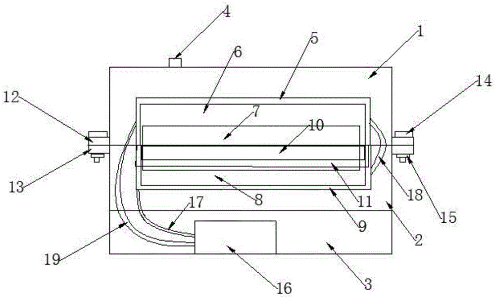
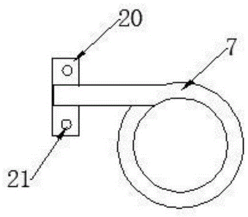
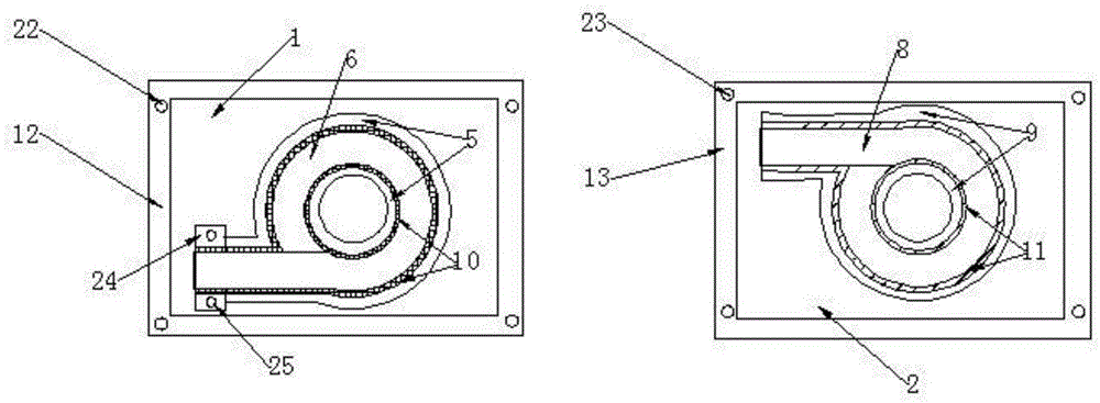
[0021] Such as figure 1 , figure 2 , image 3 As shown, a kind of turbocharger manufacturing mold of the present invention comprises upper mold 1, lower mold 2, base 3, feed inlet 4, upper mold cooling interlayer 5, upper mold cavity 6, mold core 7, lower mold Cavity 8, lower mold cooling interlayer 9, inserting plate 10, inserting plate groove 11, upper mold fixed side 12, lower mold fixed side 13, fixing screw 14, nut 15, cooling thermostat 16, cooling medium input pipe 17, connecting pipe 18. Cooling medium output pipe 19, first fixing plate 20, first mold core fixing hole 21, upper mold fixing hole 22, lower mold fixing hole 23, second fixing plate 24, second mold core fixing hole 25.

[0022] The base 3 is fixed with a lower mold 2, the lower mold 2 is provided with a mold core 7, the mold core 7 is provided with an upper mold 1, and the upper end of the upp...


PUM


Abstract

The invention provides a mold for manufacturing a turbocharger. The mold comprises an upper mold body, a lower mold body, a base, a feed port, an upper mold body cooling interlayer, an upper mold body cavity, a mold core, a lower mold body cavity, a lower mold body cooling interlayer, an inserting plate, an inserting plate groove, an upper mold body fixing edge, a lower mold body fixing edge, fixing screws, nuts and a cooling thermostat; the lower mold body is arranged on the base, the mold core is arranged on the lower mold body, the upper mold body is arranged on the mold core, the feed port is formed in the upper end of the upper mold body, the upper mold body fixing edge is fixedly arranged on the outer edge of the upper mold body, the upper mold body cavity is formed in the upper mold body, the inserting plate is arranged on the outer edge of the upper mold body cavity, the upper mold body cooling interlayer is arranged on the outer edge of the inserting plate, the lower mold body fixing edge is fixedly arranged on the outer edge of the lower mold body, the lower mold body cavity is formed in the lower mold body, the inserting plate groove is formed in the outer edge of the lower mold body cavity, the lower mold body cooling interlayer is arranged on the outer edge of the inserting plate groove, and the cooling thermostat is arranged below the base. The mold has the advantages of being high in efficiency, low in cost and good in product quality.

Description

technical field [0001] The invention belongs to the technical field of turbocharger equipment, in particular to a mold for manufacturing a turbocharger. Background technique [0002] At present, turbocharging technology is widely used in many fields such as machinery and vehicles. The turbocharger increases the air intake density of the engine by compressing air, increases the intake air volume, and makes the engine powerful. The turbocharger housing is a must for the turbocharger. It is an indispensable and important component, and its manufacturing process is highly valued. The existing shell manufacturing is generally carried out using a casting mold. The molten raw material is injected into the mold and cooled to obtain the shell product. Due to the gaps in the mold, the shell is usually produced. There are burrs or air leakage. In addition, a large amount of water is used for cooling, which not only consumes a lot of water, but also has a slow cooling rate, and it is di...

Claims


Application Information

Patent Timeline
IPC IPC(8): B22C9/24B22D27/04
CPCB22C9/24B22D27/04
Inventor 郭宗强
Owner TIANJIN RUIPU TIANSHENG AUTO PARTS MFG
Why Eureka
Try Eureka