Bag clamping device for open bag automatic filling machine

An open bag and filling machine technology, which is applied in packaging and other directions, can solve the problems of affecting the working environment, troublesome production, and the overall structure of the open bag automatic filling machine is not simple, etc., and achieves the effect of meeting the requirements of cleanliness and concise structure

Active Publication Date: 2017-09-01
CHANGSHU SANHE PRECISION MACHINERY & TECH CO LTD
View PDF7 Cites 10 Cited by
  • Summary
  • Abstract
  • Description
  • Claims
  • Application Information

AI Technical Summary

Problems solved by technology

Although this structure can meet the requirement that the discharge pipe (the patent name is "discharging sleeve") of the structural system of the discharge device is always aligned with the center of the bag opening and ensures smooth discharge, but the complex structure is its shortcoming. For example, it needs to be equipped with A bulky and troublesome material receiving box makes the overall structure of the open bag automatic filling machine less concise
Especially because the filling and discharging bag clamping mechanism recommended by this patent does not have the effect of making the two sides of the middle area of ​​the pocket opening of the open-mouth bag repel towards the direction away from each other, so that the unloading of the structural system of the unloading mechanism The feeding state of the tube is out of the bag instead of into the bag. The self-evident lack of out of the bag is easy to cause dust dispersion, which affects the working environment on the one hand and wastes resources on the other hand.

Method used


Image

  • Bag clamping device for open bag automatic filling machine
  • Bag clamping device for open bag automatic filling machine
  • Bag clamping device for open bag automatic filling machine

Examples


Embodiment Construction

[0026] In order to enable the public to understand the technical essence and beneficial effects of the present invention more clearly, the applicant will describe in detail the following examples, but the description of the examples is not a limitation to the solution of the present invention. All equivalent transformations that are only formal but not substantive should be regarded as the scope of the technical solution of the present invention.

[0027] In the following descriptions, all concepts involving directionality or orientation of up, down, left, right, front and rear are based on figure 1 As far as the position and state of the present invention are concerned, it cannot be understood as a special limitation on the technical solution provided by the present invention.

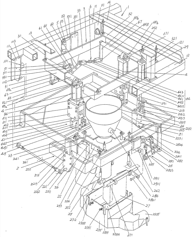
[0028] See figure 1 , shows a frame 1 and a feeding mechanism 2 belonging to the structural system of the open-mouth bag automatic filling machine. The frame 1 is supported on the floor of the place ...


PUM


Abstract

The invention provides a bag clamping device of an automatic open bag filling machine and belongs to the technical field of packaging machinery. The automatic open bag filling machine comprises a machine frame and a blanking mechanism. The bag clamping device comprises a bag clamping hanging rack, a pair of bag opening clamping-placing acting cylinders, a double-stroke acting cylinder and a clamping-placing acting cylinder linkage mechanism, wherein the bag clamping hanging rack is of a Chinese character 'kou' shaped frame-like structure formed by connecting a bag clamping hanging rack front frame strip, a bag clamping hanging rack rear frame strip, a bag clamping hanging rack left frame strip and a bag clamping hanging rack right frame strip, a supporting plate is arranged at the center position of the bag clamping hanging rack left frame strip, a double-stroke acting cylinder column swing arm shaft seat is arranged at the lower end of the supporting plate, the cylinder body tail portion of the double-stroke acting cylinder is fixed to the front end of a double-stroke acting cylinder fixing strip, the rear end of the double-stroke acting cylinder fixing strip is fixed to the upper end of the supporting plate, the clamping-placing acting cylinder linkage mechanism is hinged to the tail end of a double-stroke acting cylinder column, the bag opening clamping-placing acting cylinders correspond to each other, and bag opening clamping-placing devices in the bag opening clamping-placing acting cylinders are downward. The bag clamping device facilitates bagging and blanking of the blanking mechanism and meets the clean and tidy requirements of the automatic open bag filling machine.

Description

technical field [0001] The invention belongs to the technical field of packaging machinery, and in particular relates to a bag clamping device of an open bag automatic filling machine, which is matched with an open bag automatic filling and palletizing production line. Background technique [0002] The aforementioned open bag is widely used for fine chemical raw materials such as ultra-fine powder, metal ore and non-metallic ore powder, pharmaceutical and chemical raw materials, dyes, pigments, calcium carbonate, kaolin, phenolic resin and even food such as flour, seasoning, etc. Such as powder or granular material packaging. Since the open bag automatic filling machine has the advantages of high filling efficiency, accurate measurement, less manpower input and helping to reduce the work intensity of workers, it is widely used in the production industry not limited to the aforementioned products. [0003] As known in the industry, the main functions of the aforementioned op...

Claims


Application Information

Patent Timeline
Patent Type & Authority Patents(China)
IPC IPC(8): B65B43/54B65B43/30
CPCB65B43/30B65B43/54
Inventor 程国清
Owner CHANGSHU SANHE PRECISION MACHINERY & TECH CO LTD
Why Eureka
Try Eureka