Check patentability & draft patents in minutes with Patsnap Eureka AI!

Manufacturing technology of electrowetting display device front plate

A technology of electrowetting display and preparation process, applied in the field of electrowetting, which can solve the problems of complex preparation process, time cost and capital cost of electrowetting devices

Active Publication Date: 2016-05-25
ACADEMY OF SHENZHEN GUOHUA OPTOELECTRONICS +2
View PDF5 Cites 0 Cited by
  • Summary
  • Abstract
  • Description
  • Claims
  • Application Information

AI Technical Summary

Problems solved by technology

Among them, the material from the substrate to the pixel wall is solid, or the cured material is different from liquid materials such as ink and water. The preparation process is more complicated, such as sputtering of the conductive layer, coating and baking of the hydrophobic layer, and coating and baking of the pixel wall. Photolithography, etc., all need to go through a multi-step process and use a variety of more complex instruments, which greatly increases the time cost and capital cost of electrowetting devices.

Method used


Image

  • Manufacturing technology of electrowetting display device front plate
  • Manufacturing technology of electrowetting display device front plate
  • Manufacturing technology of electrowetting display device front plate

Examples


Embodiment Construction

[0024] The concept, specific structure and technical effects of the present invention will be clearly and completely described below in conjunction with the embodiments and accompanying drawings, so as to fully understand the purpose, features and effects of the present invention. Apparently, the described embodiments are only some of the embodiments of the present invention, rather than all of them. Based on the embodiments of the present invention, other embodiments obtained by those skilled in the art without creative efforts belong to The protection scope of the present invention. The various technical features in the invention can be combined interactively on the premise of not conflicting with each other.

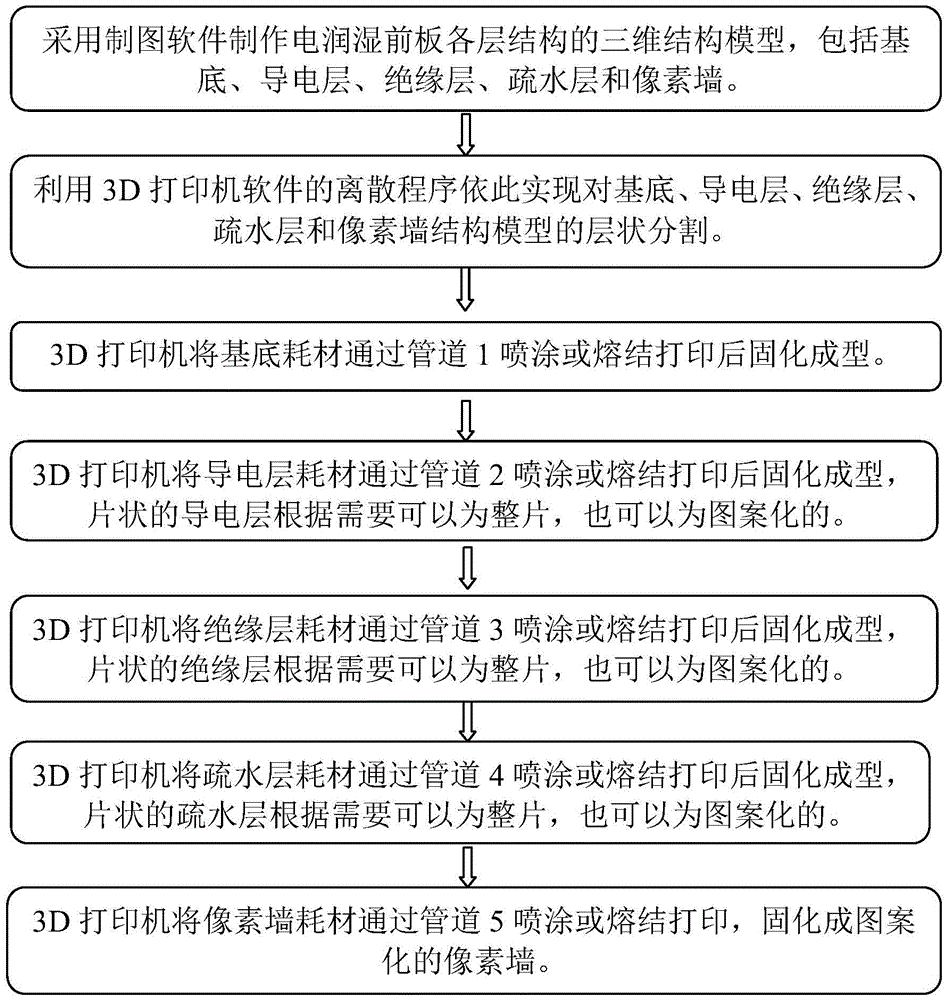
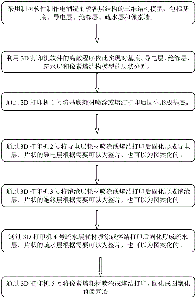
[0025] The process flow of the front plate of the electrowetting display device of the present invention is as follows: figure 1 and figure 2 shown, including:

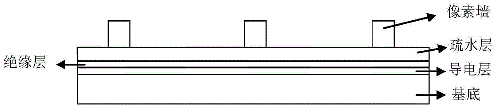
[0026] Firstly, a three-dimensional structural model of each layer structure of the front plate of the...


PUM


Abstract

The invention discloses a manufacturing technology of an electrowetting display device front plate. According to the technology, drawing software is employed to manufacture a three-dimensional structure model of each structure layer of the electrowetting display device front plate; a discrete program of 3D printer software is utilized to realize segmentation of the three-dimensional structure models, and the three-dimensional structure models are divided into multiple layers of sheet structures; the 3D printer is utilized to realize spraying or fritting of consumables of each structure layer, so the sheet structures are printed, after curing and molding, distribution of each layer of a substrate is realized, and the electrowetting display device front plate is then acquired. The manufacturing technology is advantaged in that material sources are wide, cost is low, simplification of the technology is realized, and equipment and manpower cost can be further reduced.

Description

technical field [0001] The invention relates to the field of electrowetting, in particular to a preparation process for a front plate of an electrowetting display device. Background technique [0002] The electrowetting display device includes a fluid chamber and an electrode structure, wherein the fluid chamber contains a non-conductive first fluid (alkane, etc.), a conductive second fluid (water or salt solution), and the fluids are in contact with each other and are immiscible. For example, an electrowetting display device is described in patent CN102792207A, which includes two support plates, and a wall pattern, that is, a pixel wall, is set on one of the support plates. The area formed by the pixel lattice surrounded by the pixel wall is the display area. , the electrowetting display device produces a display effect on this display area. The non-conductive first fluid is filled in the display area formed by the pixel walls, and the surrounding pixel walls are used to p...

Claims


Application Information

Patent Timeline
IPC IPC(8): G02B26/00H01L21/77
CPCG02B26/00G02B26/005H01L21/77
Inventor 周国富窦盈莹朱智星李发宏水玲玲罗伯特·安德鲁·海耶斯
Owner ACADEMY OF SHENZHEN GUOHUA OPTOELECTRONICS
Features
  • R&D
  • Intellectual Property
  • Life Sciences
  • Materials
  • Tech Scout
  • Unparalleled Data Quality
  • Higher Quality Content
  • 60% Fewer Hallucinations
Learn More