Standby control for machine tools

A technology for standby control and machine tools, applied in the field of machine tool control or machine tools, and can solve problems such as non-consideration

Active Publication Date: 2016-05-25
GF MACHINING SOLUTIONS AG
View PDF11 Cites 2 Cited by
  • Summary
  • Abstract
  • Description
  • Claims
  • Application Information

AI Technical Summary

Problems solved by technology

Current standby controls for machine tools do not take this fact into account

Method used


Image

  • Standby control for machine tools

Examples


Embodiment Construction

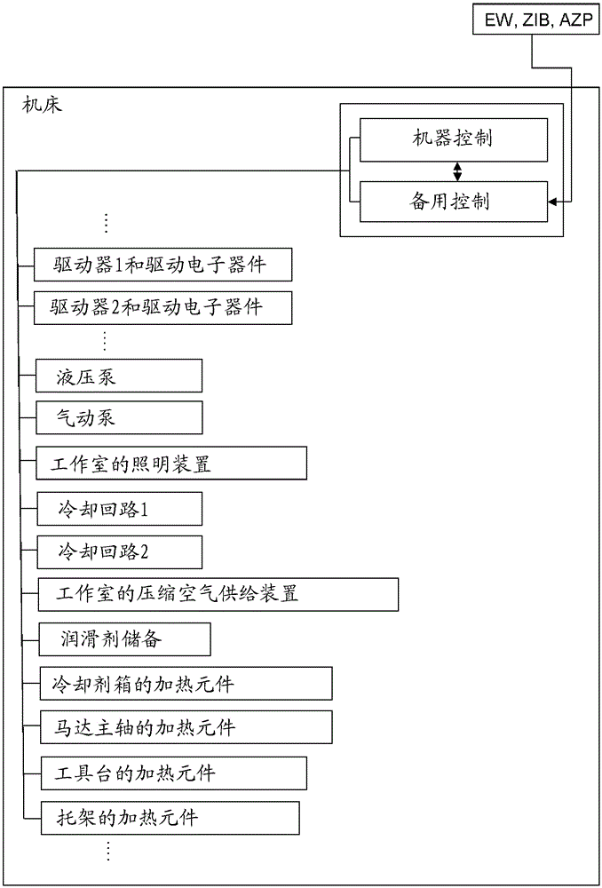
[0049] As shown by way of example in the figures, the standby control is part of the superordinate control system of the machine tool. Standby controls are also linked to normal machine tool controls. As shown in the attached figure, the backup control can be connected to many or individual power consuming components of the machine tool. These energy-consuming components are preferably elements / modules whose temperature or operation (eg in the case of fans) significantly or significantly affects the machining accuracy of the machine tool. The standby control according to the invention activates or deactivates the components given individually as required. In this way, standby control can affect the thermal state of the machine or critical machine areas during non-operational periods of the machine (or when standby mode is active) and ensure that the The desired machining accuracy of the machine tool (predetermined by entering the value EW) is retrieved in a precise manner. ...


PUM


Abstract

The invention relates to a standby control for machine tools for regulating the energy consumption of individual energy consuming components of the machine tool during the non-operation / standby phase of the machine tool. When the standby control starts, individual one of the power-consuming components is closed, so that the precision condition or precision of the individual components is adjusted during the non-operation time of the machine tool, therefore the machining accuracy of the entire machine tool is adjusted. When the machine tool starts, the starting or closing of the power-consuming components is executed through determining an input value EW, the input value EW can have electric sliding control with visual mode and corresponding to the expected machine precision.

Description

technical field [0001] The invention relates to a backup control for a machine tool, and a correspondingly designed machine tool control or machine tool. Background technique [0002] It is known to equip machine tools with backup controls that regulate the energy consumption of the machine tool. As far as the known standby mode is concerned, the various components of the machine tool (drives, controls, cooling, hydraulic transmission, etc.) . [0003] Patent specification EP2149828B1 describes a multi-stage disconnection mechanism for machines with reduced energy consumption. So a machine has states: "off", "sleep mode" (supply power to overriding controls only), "standby" (applies voltage to controls for drives, lights, etc., e.g. 24 volts), "ready for production" (all production-related components, such as drives and auxiliary units, receive power, eg 380 volts), "production" (drives draw the energy required for the machining operation, and auxiliary units run continuo...

Claims


Application Information

Patent Timeline
Patent Type & Authority Applications(China)
IPC IPC(8): G05B19/042B23Q11/00B23Q11/12
CPCB23Q11/00B23Q11/12G05B19/0428G05B2219/25289G05B2219/25286G05B2219/34306G05B19/042G05B2219/32021Y02P70/10Y02P90/02G05B19/18G05B2219/34344
Inventor J-P.贝苏彻特M.蒙施M.科兹
Owner GF MACHINING SOLUTIONS AG
Why Eureka
Try Eureka