Laser guiding device for underwater docking

A laser guidance, underwater docking technology, applied in vehicle position/route/altitude control, non-electric variable control, instruments, etc., can solve the problems of low sonar guidance accuracy, complex solution, and high implementation cost. Improve the success rate of search, increase the success rate, increase the distance and effect of imaging

Inactive Publication Date: 2016-05-25
QINGDAO ACAD FOR OPTO ELECTRONICS ENG
View PDF7 Cites 7 Cited by
  • Summary
  • Abstract
  • Description
  • Claims
  • Application Information

AI Technical Summary

Problems solved by technology

Although this method has a long range, the accuracy of sonar guidance is low, and a complex mechanical structure is required to ensure the reliability of docking in the short-distance docking type
The other is the guided docking method based on visual servoing. This method requires high-quality imaging of landmarks and high-precision data measurement algorithms as technical support, so the implementation cost is high and the solution is more complicated.

Method used


Image

  • Laser guiding device for underwater docking
  • Laser guiding device for underwater docking

Examples


Embodiment 1

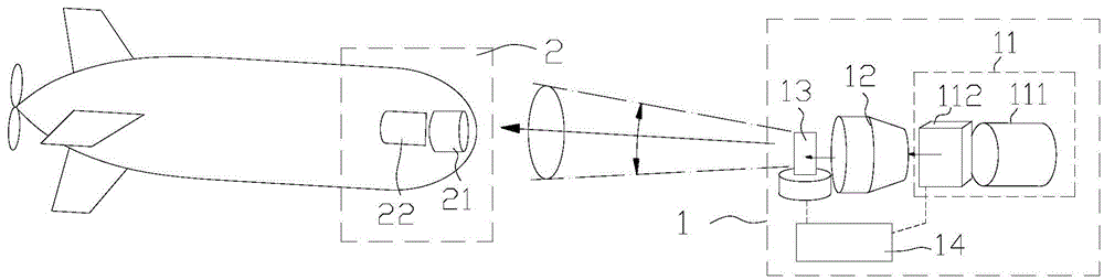
[0016] exist figure 1 Among them, the device includes a cone-shaped laser scanning module 1 and a laser receiving module 2;

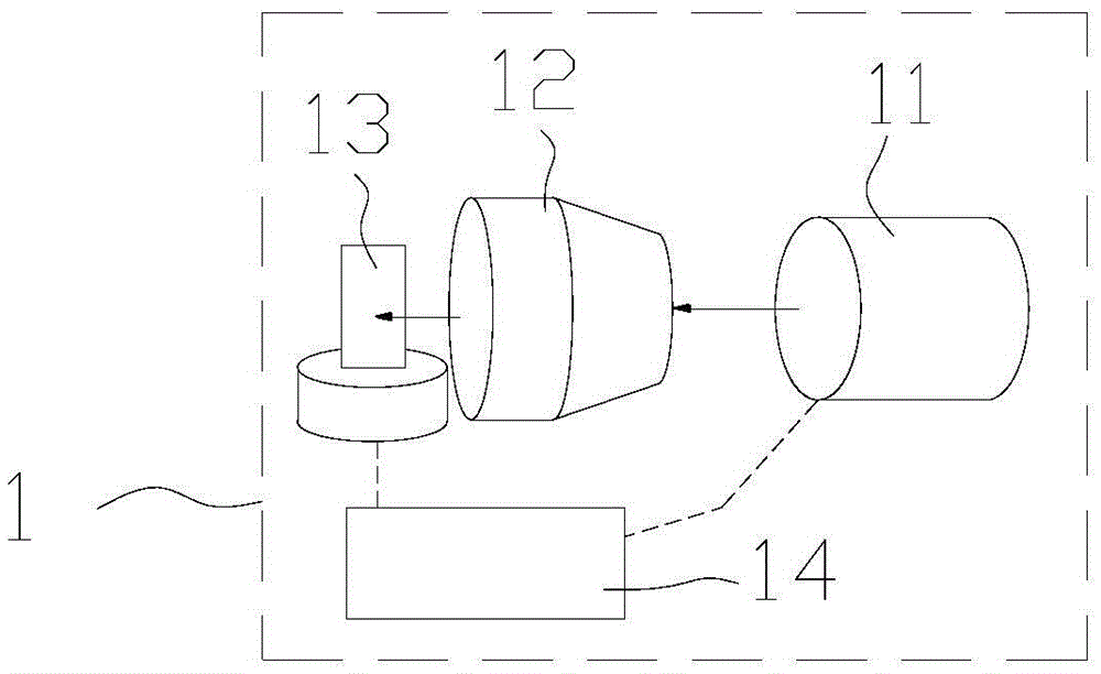
[0017] The conical laser scanning module 1 is installed on the docking platform, and includes an external modulation laser module 11, a parallel collimation module 12, a high-speed two-dimensional scanning galvanometer 13 and a central processing module 14, and the parallel collimation module 12 has the same optical axis Fixedly installed in front of the modulating laser module 11, the high-speed two-dimensional scanning galvanometer 13 is fixedly installed in front of the parallel collimation module 12, and the external modulation laser module 11 is installed from the inside to the outside on the same optical axis as the laser 111 and the light modulation module 112 The central processing module 14 controls the light modulation module 112 to encode the emission angle information of the laser beam emitted by the laser 111 .

[0018] The laser receiving...

Embodiment 2

[0021] exist figure 2 Wherein, the modulatable laser module 11 is an internally modulated laser module, and the central processing module 14 controls the modulatable laser module 11 to emit pulses to realize laser beam emission angle information encoding.

[0022] When the underwater vehicle navigates to the underwater docking platform area through underwater acoustics, the underwater docking platform starts to guide it, and the central processing module 14 controls the modulatable laser module 11 to emit a laser beam with emission angle information code and control the high-speed The two-dimensional scanning galvanometer 13 changes the emitting angle of the laser beam, continuously changes the encoding information of the emitting angle of the guiding laser beam and the emitting angle to form a spatial conical scanning laser beam, and the underwater vehicle can receive the laser beam within this range , the photodetector 22 completes the acquisition of the laser beam angle co...


PUM


Abstract

The invention discloses a laser guiding device for underwater docking. The device comprises a can-be-modulated laser module, a parallel collimation module, a high speed two-dimensional scanning galvanometer, a central processing module and a laser reception module, wherein the high speed two-dimensional scanning vibrating mirror is controlled by the central processing module for making the can-be-modulated laser module emit laser to form a spatial conic scanning laser beam, an angle code of the spatial conic scanning laser beam is acquired through a photoelectric detector, the angle code acquired by the photoelectric detector is read and analyzed by an underwater navigation device end, and then the angle information relative to a docking platform can be acquired through querying the pre-set information, self attitude is continuously adjusted according to the angle information, the underwater navigation device end moves to the docking platform to accomplish docking, and the underwater searching success rate is improved.

Description

technical field [0001] The invention relates to a laser guiding device, in particular to a laser guiding device for underwater docking. Background technique [0002] With the development of science and technology, more and more attention is paid to the development of the ocean. Due to the limitation of human physiological conditions, most of the work of underwater development needs to be completed with the help of underwater equipment. As an indispensable Tools, more and more valued, have broad application prospects and important scientific research value. However, limited by the size and mass, the energy carried by the underwater vehicle is very limited, and it must establish a connection with the docking platform to replenish energy and exchange information during long-term operations. At present, there are two commonly used underwater docking guidance methods. One is the sonar-based navigation-guidance-docking integration method, which directly uses the navigation equipm...

Claims


Application Information

Patent Timeline
IPC IPC(8): G05D1/08
CPCG05D1/0875
Inventor 温亚楠田维坚朱建鑫
Owner QINGDAO ACAD FOR OPTO ELECTRONICS ENG
Why Eureka
Try Eureka