Generating method for printing path used for light three-dimensional model printing

A technology of 3D printing and printing path, applied in the direction of digital output to printing unit, special data processing application, data processing input/output process, etc., can solve problems such as affecting molding quality and efficiency, over-piling, low printing model strength, etc. , to achieve the effect of improving mechanical properties, improving structural strength, and improving overall mechanical performance

Active Publication Date: 2016-05-25
江苏航浦国创复材研究院有限公司
View PDF5 Cites 13 Cited by
  • Summary
  • Abstract
  • Description
  • Claims
  • Application Information

AI Technical Summary

Problems solved by technology

Three groups of parallel discontinuous straight-line paths are used to construct the honeycomb scanning path. Since this method uses discontinuous scanning in three directions, there are three repeated scans at the end of the path, which makes the end point over-accumulated. At the same time, discontinuous scanning in three directions is used. It also causes a large number of idle strokes and knife jumps on the cutting layer, which seriously affects the molding quality and efficiency
Ponnusamy.P and GurunathanSaravanaKumar et al. mentioned in Virtual and Physical Prototyping, 2009, 4(3): 165-180, "Personalised bone issue en

Method used


Image

  • Generating method for printing path used for light three-dimensional model printing
  • Generating method for printing path used for light three-dimensional model printing
  • Generating method for printing path used for light three-dimensional model printing

Examples


Embodiment

[0045] Such as Figure 1-7 As shown, a method for generating a printing path for lightweight 3D printing of a model in this embodiment performs the following steps:

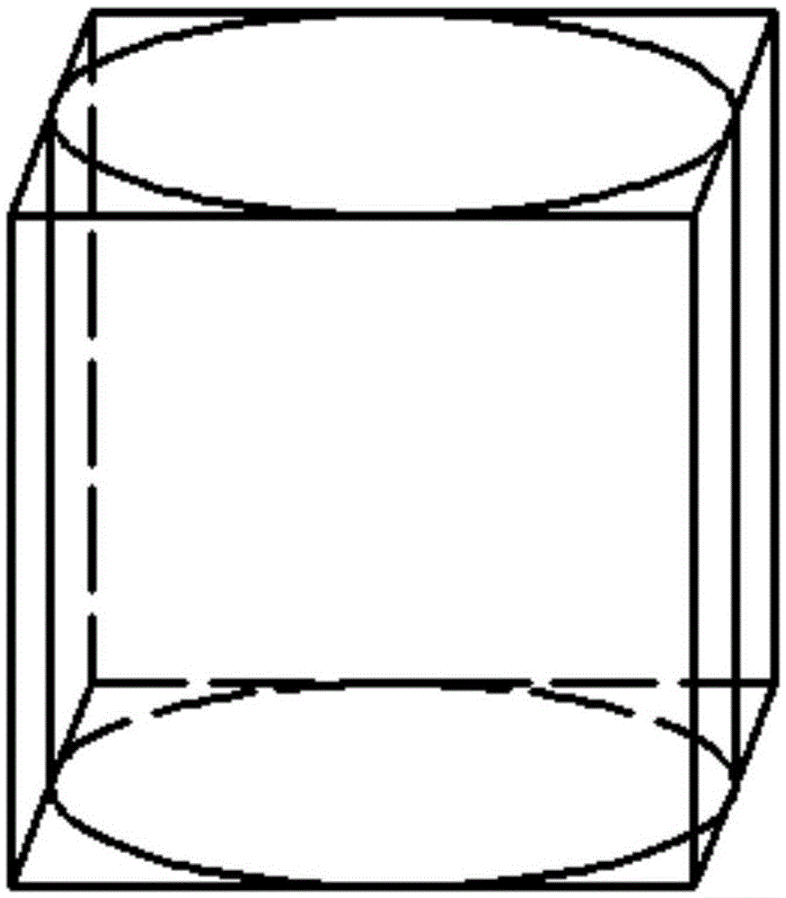
[0046] 1) if figure 2 As shown, the minimum bounding box of the model is determined according to the size of the model; the minimum bounding box in this embodiment is generally a cuboid, or a cylinder in special cases, depending on whether the shape of the enclosed original model is regular, and the minimum All sides of the bounding box are tangent to the outer contour of the original model;

[0047] 2) slice the bounding box to form multiple identical slice layers;

[0048] 3) establishing a Cartesian coordinate system on the same plane as the slice layer;

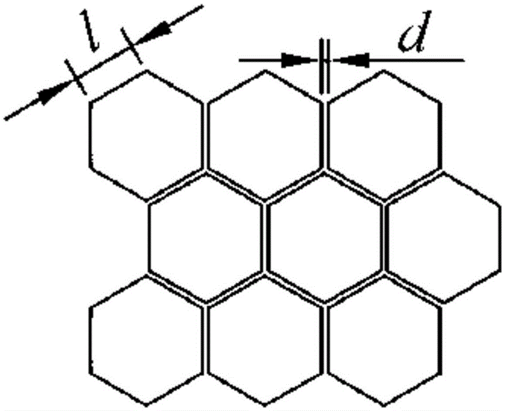
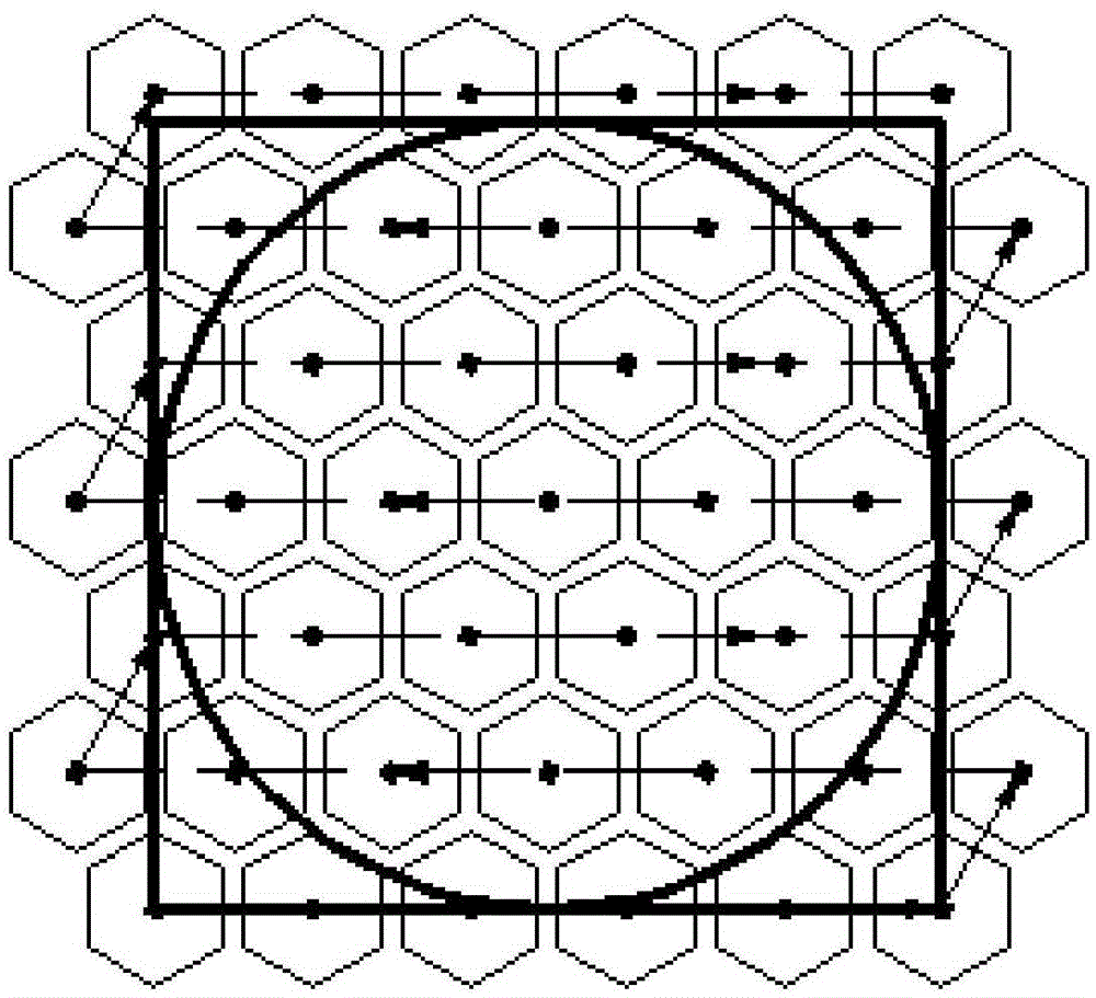
[0049] 4) if image 3 As shown, starting from the minimum value point of the slice layer in the Cartesian coordinate system, a number of honeycomb path units with a side length of l and a distance of d between each other are filled in the Cartesian coor...


PUM


Abstract

The invention relates to a generating method for a printing path used for light three-dimensional model printing and belongs to the technical field of forming. The method comprises the following steps that 1, a minimum bounding box of a model is determined according to the size of the model; 2, the bounding box is sliced to form multiple same slice layers; 3, a rectangular coordinate system is set up on the same plane of the slice layers; 4, with a minimal value point of the rectangular coordinate system where the slice layers are located as a starting point, the rectangular coordinate system is filled with multiple cellular path units with the side length being 1 and the gap between the cellular path units being d until the whole slice layers are covered; 5, the slice layers are tailored according to actual filling areas of all the slice layers to obtain the printing path of the slice layers. The filling path for light three-dimensional printing is generated, by filling the slice layers with the complete cellular path units, the problem of multi-end-point piling caused by repeated wiring is avoided, and the problem that the printing structure is irregular is avoided.

Description

technical field [0001] The invention relates to a method for generating a printing path, which belongs to the technical field of forming. Background technique [0002] With the continuous development of 3D printing manufacturing technology, people have higher and higher requirements for energy saving, consumption reduction, and rapid manufacturing. The lightweight structure with the goal of weight reduction and high performance has attracted more and more attention. At present, the generation methods of lightweight structures based on 3D printing technology mainly fall into the following two categories: The first type is to design lightweight structures using geometric solid modeling before slicing the model, such as designing complex holes or trusses inside the model structure. The second type is the scanning path planning after the model is sliced. By filling some regular mesh paths (such as honeycomb scanning paths, rhombus scanning paths, and fractal scanning paths) ins...

Claims


Application Information

Patent Timeline
IPC IPC(8): G06F17/50G06F3/12
CPCG06F3/1208G06F3/1219G06F3/1241G06F30/367
Inventor 戴宁崔海华吴长友程筱胜
Owner 江苏航浦国创复材研究院有限公司
Why Eureka
Try Eureka