
Sound source positioning method and apparatus and time delay estimation method and apparatus

A technology of time delay estimation and sound source, which is used in positioning, measuring device, speech analysis, etc., and can solve problems such as increased positioning error and Gaussian noise pollution.

Inactive Publication Date: 2016-05-25
北京爱宾果科技有限公司
View PDF9 Cites 9 Cited by
  • Summary
  • Abstract
  • Description
  • Claims
  • Application Information

AI Technical Summary

Problems solved by technology

[0005] In view of this, the present application provides a method and device for sound source localization and its time delay estimation method and device, to overcome the signal time delays in the time-domain high-order statistics method and generalized cross-correlation-spectrum weighting method in the prior art. The problem of increased positioning error due to the influence of aliasing peaks and Gaussian noise pollution around the extension

Method used


Image

  • Sound source positioning method and apparatus and time delay estimation method and apparatus
  • Sound source positioning method and apparatus and time delay estimation method and apparatus
  • Sound source positioning method and apparatus and time delay estimation method and apparatus

Examples


Embodiment 1

[0062] Embodiment 1 of the present application provides a delay estimation method, such as figure 1 as shown, figure 1 It is a flow chart of a delay estimation method provided in Embodiment 1 of the present application. The delay estimation method includes:

[0063] S101: Perform two-stage noise reduction processing on the sound signal from the received sound source to obtain a noise reduction signal;

[0064] The sound signal propagation equation is:

[0065] x 1 (t)=s(t)+n 1 (t),

[0066] x 2 (t)=as(t+t)+n 2 (t),

[0067] where x 1 (t) is the original reference signal, that is, the sound signal received by the first microphone, x 2 (t) is the sound signal received by the second microphone, which is called the original delayed signal, a is the relative amplitude attenuation, that is, the attenuation amplitude relative to s(t), τ is the relative time delay, and s(t) is the source signal , n 1 (t) and n 2 (t) are the noise signals of the two microphone sound transm...

Embodiment 2

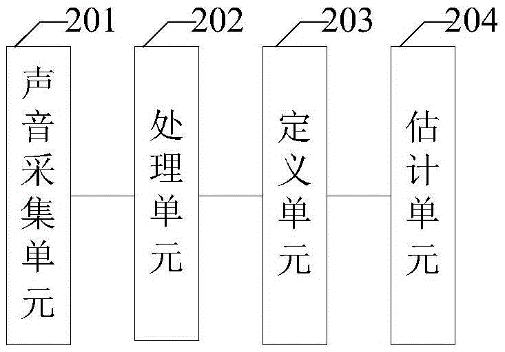
[0090] On the basis of Embodiment 1, Embodiment 2 of the present application provides a delay estimation device, such as figure 2 as shown, figure 2 It is a schematic structural diagram of a delay estimation device provided in Embodiment 2 of the present application. The delay estimation device includes: a sound collection unit 201, a processing unit 202, a definition unit 203 and an estimation unit 204, wherein,

[0091] Sound collection unit 201, for collecting the sound signal that sound source sends;

[0092] The processing unit 202 is configured to perform two-stage noise reduction processing on the sound signal collected by the sound collection unit 201 to obtain a noise reduction signal;

[0093] In this application, the processing unit includes: a first processing unit and a second processing unit, wherein,

[0094] The first processing unit is used to perform local and global noise reduction processing on the signal by using a channel filter, reduce noise interfe...

Embodiment 3

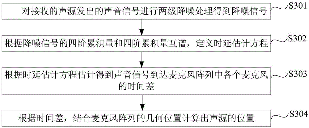
[0109] Embodiment 3 of the present application provides a sound source localization method, such as image 3 as shown, image 3 A sound source localization method provided in Embodiment 3 of the present application includes:

[0110] S301: Perform two-stage noise reduction processing on the sound signal from the received sound source to obtain a noise reduction signal;

[0111] In this application, performing two-stage noise reduction processing on the sound signal from the received sound source to obtain the noise reduction signal includes:

[0112] S1: use the channel filter to perform local and global noise reduction processing of the signal, reduce the noise interference in the sound signal, and obtain a preliminary noise reduction signal;

[0113] S2: superimpose the whitening weight function k on the preliminary noise reduction signal, reduce the false peak amplitude, increase the delay peak value, and obtain the noise reduction signal.

[0114] S302: Define a time de...


PUM


Abstract

The application provides a sound source positioning method and apparatus and a time delay estimation method and apparatus. The time delay estimation method comprises: two-stage noise reduction processing is carried out on a received acoustical signal sent by a sound source to obtain a noise reduction signal; according to a four-order cumulant and a four-order cumulant cross spectrum of the noise reduction signal, a time delay estimation equation is defined; and according to the time delay estimation equation, time differences of arrival of acoustical signal at all microphones in a microphone array are estimated and obtained. According to the time delay estimation method, with the two-stage noise reduction processing and the four-order cumulant cross spectrum, influences of the noises and the interference are reduced; the time delay can be estimated accurately; and a problem that the sound source positioning error is increased due to the confused peak value around the acoustical signal delay and the Gaussian noise pollution influence according to the time-domain high-order statistics method and the generalized cross correlation-spectrum weight method can be solved.

Description

technical field [0001] The present application relates to the technical field of sound source localization, and in particular to a sound source localization method and device and a time delay estimation method and device thereof. Background technique [0002] Microphone sound source localization technology uses a microphone to pick up sound signals, and uses digital signal processing technology to analyze and process them, and then determine and track the spatial position of the sound source. For indoor complex scenes, the position of the sound source can be estimated in real time and accurately, and this can be used as the basis for adjusting the pose of the robot body, so that the robot body can actively adjust the pose according to the position of the sound source, and move the body towards the position of the sound source . If there are multiple sound sources, the main sound source can be intelligently selected, and the influence of the secondary sound source can be sup...

Claims


Application Information

Patent Timeline
Patent Type & Authority Applications(China)
IPC IPC(8): G10L21/0208G10L21/0216G10L21/0224G01S5/18
CPCG10L21/0208G01S5/18G10L21/0216G10L21/0224G10L2021/02166
Inventor 闵海波侯博
Owner 北京爱宾果科技有限公司
Learn More