Preparation method of flexible battery

A flexible battery, flexible electricity technology, applied in secondary battery manufacturing, batteries, circuits, etc., can solve the problems of increasing the number of batteries in series and parallel, no advantages, flexibility and freedom restrictions, etc., to increase the capacity or The effect of output voltage, reducing the number of packaging, and improving packaging efficiency

Active Publication Date: 2016-05-25
HUNAN LIFANG NEW ENERGY SCI & TECH
View PDF4 Cites 13 Cited by
  • Summary
  • Abstract
  • Description
  • Claims
  • Application Information

AI Technical Summary

Problems solved by technology

However, this traditional method often increases the number of batteries connected in series and parallel, and at the same time complicates the battery assembly process and the charge and discharge management system (PCM).
On the other hand, the smaller the battery space is divided, that is, the smaller the size of a small battery cell, the lower its energy density, which in turn leads to problems such as short working hours of smart devices and reduced customer experience in the same unit space.
[0004] The Chinese patent with the patent number CN203026608U discloses a bendable flexible battery in which battery cells are connected in parallel and packaged in a flexible packaging bag. This patent provides some solutions for the power supply design scheme of wearable smart devices; but its The cell unit itself of the disclosed flexible battery is still not bendable. In addition, the bending degree of the entire battery is directly related to the number of single cells connected in parallel and the width of the single cells, and its flexibility and freedom are greatly restricted. At the same time, due to the limitation of the parallel connection between its single cells, its output voltage has no advantage compared with traditional single cells

Method used


Image

  • Preparation method of flexible battery
  • Preparation method of flexible battery
  • Preparation method of flexible battery

Examples


Embodiment 1

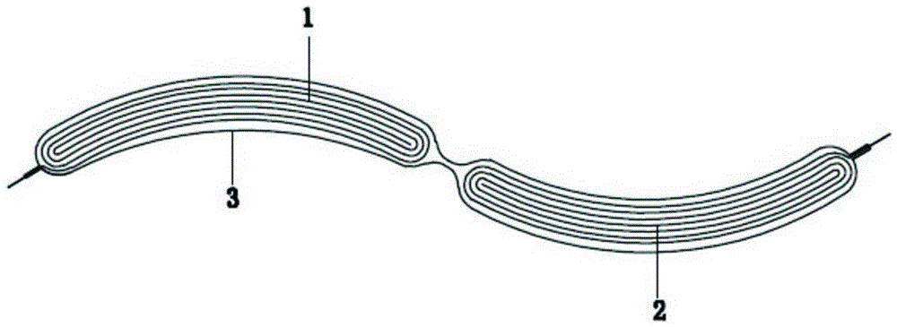
[0029] like figure 1 As shown, two electrically connected flexible battery units 1 and 2 are prepared, and the flexible battery units 1 and 2 are wound from positive pole pieces, negative pole pieces and a separator between them, and are coated with an insulating layer. It is insulated, and the positive and negative conductive terminals made of metal aluminum are shared between the two flexible battery units 1 and 2; the two flexible battery units 1 and 2 are connected in series and wrapped in a flexible packaging bag 3 Inside, a gap of 5 mm is reserved between the two flexible battery units 1 and 2, and the side and top edges of the flexible packaging bag 3 are heat-sealed; since the above two flexible battery units 1 and 2 can use the same electrolyte, so there is no need to separate the two flexible cell units 1 and 2 by heat sealing, and the electrolyte is directly injected into the flexible packaging bag 3, so that an electrolytic cell containing the electrolyte is formed...

Embodiment 2

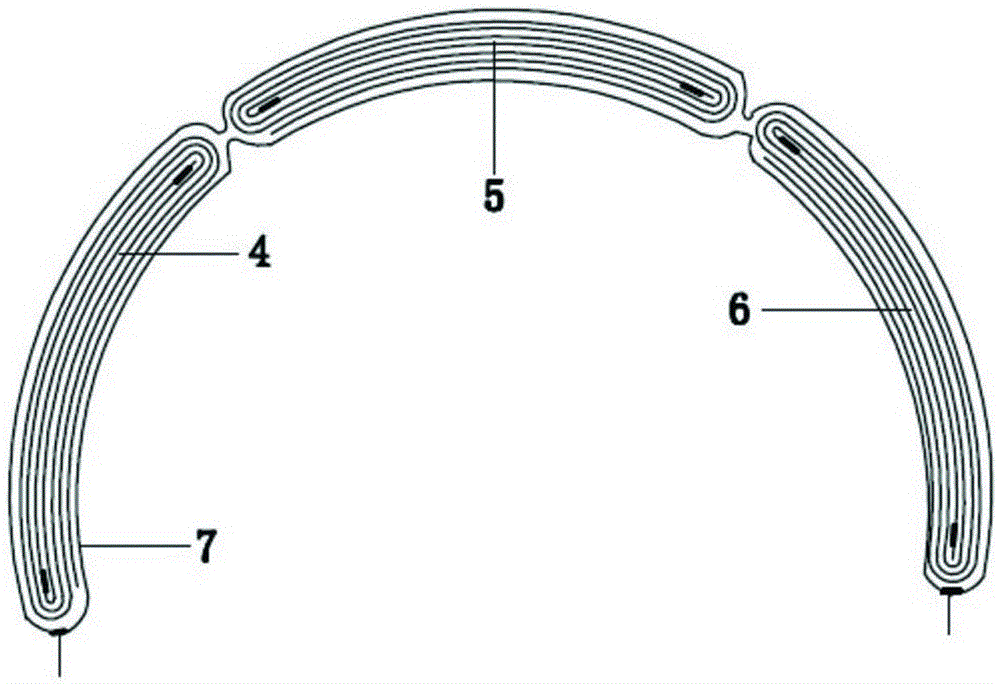
[0031] like figure 2 As shown, three electrically connected flexible battery units 4, 5, 6 are prepared, and the flexible battery units 4, 5, 6 are wound from positive pole pieces, negative pole pieces and a separator between them, and passed through Apply insulating glue to insulate it, and share the positive and negative conductive terminals made of metal nickel between the three flexible battery units 4, 5, and 6; connect the three flexible battery units 4, 5, and 6 in series The form connection is wrapped in the flexible packaging bag 7, and a gap of 2 mm is reserved between the three flexible battery units 4, 5, 6, and the side and the top edge of the flexible packaging bag 7 are heat-sealed; The cell units 4, 5, and 6 can use the same electrolyte, so there is no need to separate the two flexible cell units 4, 5, and 6 by heat sealing, and the electrolyte is directly injected into the flexible packaging bag 7, and then the flexible packaging The other side of the bag 7 ...

Embodiment 3

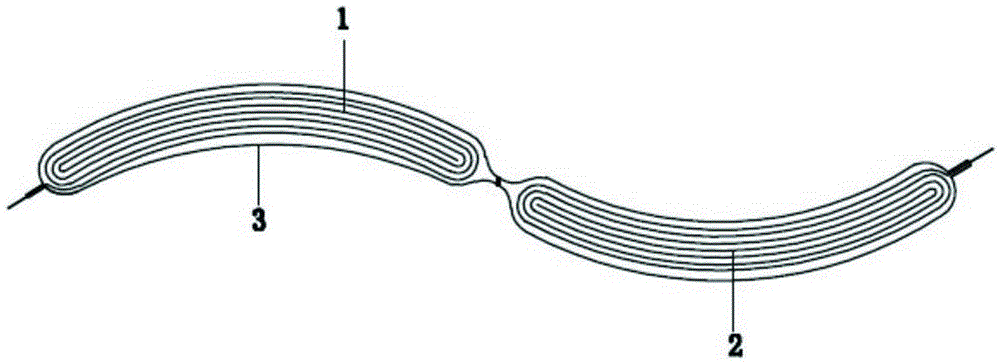
[0033] like image 3 As shown, the difference from Example 1 is that the flexible battery units 1 and 2 use different electrolytes, and heat-package is performed in the gap reserved between the flexible battery units 1 and 2, so that the flexible packaging bag 3 is formed Two electrolytic cells containing electrolytes are injected with different electrolytes into the two electrolytic cells, and then the other side of the flexible packaging bag 3 is sealed; the battery is formed, and the gas generated by the formation is collected in the flexible packaging bag 3, then puncture the airbag bag to release the gas generated by chemical formation, cut off the airbag bag and the redundant side, and finally obtain a flexible battery.


PUM


Abstract

The invention belongs to the technical field of batteries, and particularly relates to a preparation method of a flexible battery. The method comprises the following steps: preparing at least two electrically connected flexible battery cell units, and carrying out insulating treatment; connecting and wrapping the flexible battery cell units in a flexible packaging bag in a series or parallel manner, carrying out heat-sealing on one side and the top edge; injecting an electrolyte into the flexible packaging bag and sealing the other side; carrying out formation on the battery, collecting the gas generated by formation in an air bag reserved on the flexible packaging bag and then puncturing the air bag to release the gas generated by formation; and cutting off the air bag and excessive side, and finally obtaining the flexible battery. Compared with independent package of a single flexible battery core unit, the preparation method of the flexible battery provided by the invention increases the electric capacity or output voltage of the flexible battery, reduces the packaging frequency of the flexible battery, saves the packaging material and improves the packaging efficiency.

Description

technical field [0001] The invention belongs to the technical field of batteries, and in particular relates to a preparation method of a flexible battery. Background technique [0002] As we all know, the shape of the current commercialized single lithium-ion battery mainly includes (1) the rectangular shape represented by the application in smart phones, tablet computers and other products, (2) the shape used in light electric tools, electric bicycles, Tesla electric 18650, 26650, and button battery as the representative cylinder type in products such as cars and electronic watches, (3) "knife type" and "apple type" represented by Apple music players, bluetooth earphones and other products Isoplanar shaped battery. None of the above shapes of single battery can bend itself, so it is rarely used in complex or comfortable wearable devices that require flexibility of the battery. [0003] For the current smart wearable device market, the existing traditional battery technolo...

Claims


Application Information

Patent Timeline
Patent Type & Authority Applications(China)
IPC IPC(8): H01M10/04
CPCH01M10/04H01M2220/30Y02E60/10Y02P70/50
Inventor 胡海波涂健刘凯刘克永陈振刘喜
Owner HUNAN LIFANG NEW ENERGY SCI & TECH
Why Eureka
Try Eureka