Optical transparent antenna

An antenna, transparent technology, applied in the direction of antenna, antenna parts, antenna grounding device, etc., can solve the problem that the optical transparent antenna cannot directional radiation

Inactive Publication Date: 2016-05-25
BEIJING UNIV OF POSTS & TELECOMM
View PDF3 Cites 14 Cited by
  • Summary
  • Abstract
  • Description
  • Claims
  • Application Information

AI Technical Summary

Problems solved by technology

[0005] The embodiment of the present invention discloses an optically transparent antenna to solv

Method used


Image

  • Optical transparent antenna
  • Optical transparent antenna
  • Optical transparent antenna

Examples


Embodiment Construction

[0027] The following will clearly and completely describe the technical solutions in the embodiments of the present invention with reference to the accompanying drawings in the embodiments of the present invention. Obviously, the described embodiments are only some, not all, embodiments of the present invention. Based on the embodiments of the present invention, all other embodiments obtained by persons of ordinary skill in the art without creative efforts fall within the protection scope of the present invention.

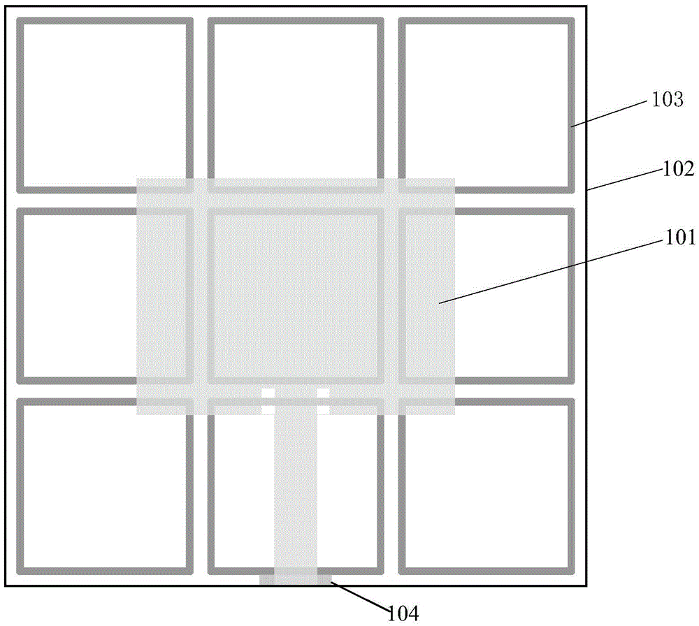
[0028] In order to solve the problem that the optically transparent antenna cannot direct radiation in the prior art, an embodiment of the present invention provides an optically transparent antenna.

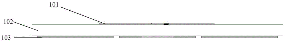
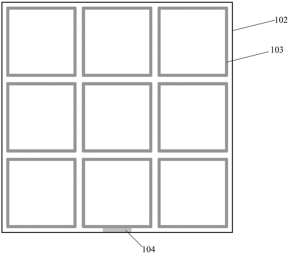
[0029] Fig. 1 (a) is the front view of a kind of optical transparent antenna provided by the embodiment of the present invention, Fig. 1 (b) is the bottom view of a kind of optical transparent antenna provided by the present invention, as Fig. 1 (a) and Fig. 1 (b) An...


PUM


Abstract

The embodiment of the invention discloses an optical transparent antenna, and the antenna comprises a three-layer structure which is formed by the sequential connection of a first layer, a second layer and a third layer. The first layer is an antenna radiator layer, the second layer is a dielectric layer with transparency, and the third layer is an antenna ground layer. The antenna radiator layer takes an ITO (indium tin oxide) film as a radiation paster, and the antenna ground layer employs a slotting-type frequency selection surface structure. According to the scheme of the invention, the frequency selection surface is a slotting type, so the frequency selection surface belongs to a band-pass frequency selection surface from the aspect of frequency attributes, the interior of a pass-band can achieve the reflection of an incident electromagnetic wave and the exterior of the pass-band displays transmission characteristics. Moreover, the frequency selection characteristics of the frequency selection surface enable the antenna to show directional characteristics when the antenna works at a pass-band of the frequency selection surface. Meanwhile, the slotting-type frequency selection surface is higher in light transmissivity. Therefore, the antenna solves a problem that an optical transparent antenna cannot achieve directional radiation in the prior art.

Description

technical field [0001] The invention relates to the field of wireless communication applications, in particular to an optically transparent antenna. Background technique [0002] With the rapid development of the wireless communication system, the application scenarios of the wireless communication system are becoming more and more abundant, so that the wireless communication system has more and more diverse requirements for antenna performance. In order to achieve good conformality, safety and stealth of the antenna so that it can be integrated in mobile terminals, satellites, automobiles and other systems that require antennas to have optical transparency, scientists have begun to pay attention to optically transparent antennas. [0003] In 1997, scientists from the National Aeronautics and Space Administration (NASA) proposed the idea of ​​using light-transparent film materials to make antennas. In 2000, the research team of N. Outaleb of Rennes 1 University in France to...

Claims


Application Information

Patent Timeline
IPC IPC(8): H01Q1/36H01Q1/38H01Q1/48H01Q1/50H01Q15/00
CPCH01Q1/364H01Q1/38H01Q1/48H01Q1/50H01Q15/0013
Inventor 姚远陈晚忠俞俊生刘小明亓丽梅陈智娇
Owner BEIJING UNIV OF POSTS & TELECOMM
Why Eureka
Try Eureka