Cable bridge applicable for compressor set

A technology for cable trays and compressor units, which is applied to electrical components and other directions, can solve problems such as electrical circuit laying, and achieve the effect of regular space arrangement, compact structure and saving base space.

Active Publication Date: 2016-05-25
SHENYANG SITE MACHINERY MFG
View PDF11 Cites 0 Cited by
  • Summary
  • Abstract
  • Description
  • Claims
  • Application Information

AI Technical Summary

Problems solved by technology

It solves the problem of electrical circuit laying of compressor unit instruments well

Method used


Image

  • Cable bridge applicable for compressor set

Examples


Embodiment 1

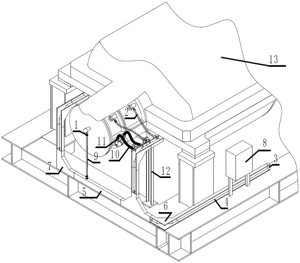
[0021] Cut the steel plates, splice and weld them into the following parts according to the following dimensions, the steel pipe size is 3 / 4 inch; the pipe joint (inner) is G3 / 4 inch; the cable bridge groove is 100 mm wide and 50 mm high; the horizontal bend connects its two right angles The length of the side is 350 millimeters and 350 millimeters; the length of its two right angles is 300 millimeters and 300 millimeters; the width of the cover plate is 100 millimeters. Finally, the bracket is welded and fixed on the base of the compressor unit to make a cable bridge.

[0022] Install the instrument on the compressor unit body or the base pipeline, and lead the cables to the bridge frame through the cable clamp sealing joint on the instrument, so that the cables are arranged in the bridge groove smoothly and beautifully, and the inside of the bridge frame can be led to the junction box terminal through the sealing joint On, hanger brackets (or pillars) for cable fixing. Afte...

Embodiment 2

[0024] Cut the steel plates, splice and weld them into the following parts according to the following dimensions, the steel pipe size is 3 / 4 inch; the pipe joint (inside) is G3 / 4 inch; the cable bridge groove is 100 mm wide and 80 mm high; the horizontal bend passes through its two right angles The length of the side is 300 mm and 250 mm; the length of its two right-angled sides is 350 mm and 300 mm; the width of the cover plate is 100 mm. Finally, the bracket is welded and fixed on the base of the compressor unit to make a cable bridge.

[0025] After installing the instrument on the compressor unit body or the pipeline on the base, the cables are led out through the terminal inside the instrument through the electrical interface of each instrument, connected to the bridge through the pipe joint through the steel pipe, and arranged in the bridge groove in a flat and beautiful way. The inside of the bridge can be passed Coupon bracket (or post) for cable fixing. After the cab...

Embodiment 3

[0027] Its structure and size are the same as embodiment 1, but it is horizontally fixed on the base of the compressor unit with the shoulder by the nut.


PUM


Abstract

A cable bridge applicable for a compressor set is characterized by comprising a vertical post, a piping connector, flexible hoses, a plug, a groove-type bridge, a cover plate, a vertical elbow, a horizontal bent pipe and a junction box, wherein (1), the piping connector is arranged at the tail end of a compressor and is used for accommodating a cable of a group of test component, one end of the cable is connected with the test component, and the other end of the cable is connected with a cable bridge groove; (2) two groups of flexible hoses are respectively arranged on the two sides of the tail segment of the compressor and used for accommodating two groups of test cables, one end of each test cable is connected with the test component, and the other ends of the test cables are connected with the cable bridge groove by two flexible hoses; (3) two steel pipes are connected to the cable bridge and finally connected to the junction box by the horizontal or vertical pipe connector; and (4) the bridge is of a groove-type structure, and the detachable cover plate is arranged on the upper surface of the groove. The whole bridge is fixed on a base of the compressor set.

Description

technical field [0001] The invention belongs to the technical field of cable or wire installation, and in particular relates to a cable bridge for laying and installing instrument electrical lines within the range of a compressor base. Background technique [0002] At present, the structure of steel pipe (commonly known as water and gas pipe) plus flexible pipe is usually used for laying instrument electrical lines within the scope of the compressor base. Cables are placed in steel pipes, and each cable passes through a steel pipe individually. In this way, the compressor instrument is often constructed with steel pipes covering the entire compressor base. Not only does it occupy the passage of the maintenance station personnel, which brings a lot of inconvenience for future maintenance and repair; but also in the installation stage of the manufacturing plant, there is also the problem of repeated disassembly and assembly of the workpiece in order not to affect the overall ...

Claims


Application Information

Patent Timeline
Patent Type & Authority Applications(China)
IPC IPC(8): H02G3/00H02G3/04
CPCH02G3/00H02G3/0418H02G3/0456
Inventor 石雪松
Owner SHENYANG SITE MACHINERY MFG
Why Eureka
Try Eureka