Coalbed methane horizontal well supercritical CO2 jet flow cavity construction and multi-segment synchronous deflagration fracturing method

A technology for horizontal wells and coalbed methane, applied in drilling equipment and methods, drilling with liquid/gas jets, mining fluids, etc., can solve the problems of difficult formation of network fractures, polluted coal seams, long construction period, etc., and increase production , Improve the permeability of coal body and the effect of improving the permeability of coal rock

Inactive Publication Date: 2016-06-01
CHINA UNIV OF PETROLEUM (BEIJING)
View PDF5 Cites 36 Cited by
  • Summary
  • Abstract
  • Description
  • Claims
  • Application Information

AI Technical Summary

Problems solved by technology

The hydraulic fracturing technology is well developed and the process is relatively mature, but there are limitations in that the construction period is long, drainage is required, the equipment is complicated, the cost is high, and the coal seam is often polluted, and most of the cracks produced are single main cracks, and it is difficult to form a network of cracks
High-energy gas fracturing is also applied in the development of coalbed methane. Explosion shock waves can create more micro-fractures in the formation, but there are limitations such as low energy and short fractures.

Method used


Image

  • Coalbed methane horizontal well supercritical CO2 jet flow cavity construction and multi-segment synchronous deflagration fracturing method
  • Coalbed methane horizontal well supercritical CO2 jet flow cavity construction and multi-segment synchronous deflagration fracturing method
  • Coalbed methane horizontal well supercritical CO2 jet flow cavity construction and multi-segment synchronous deflagration fracturing method

Examples


Embodiment

[0027] Coalbed methane horizontal well supercritical CO provided by the invention 2 The method of jet cavity creation and multi-stage synchronous deflagration fracturing may include the following specific steps:

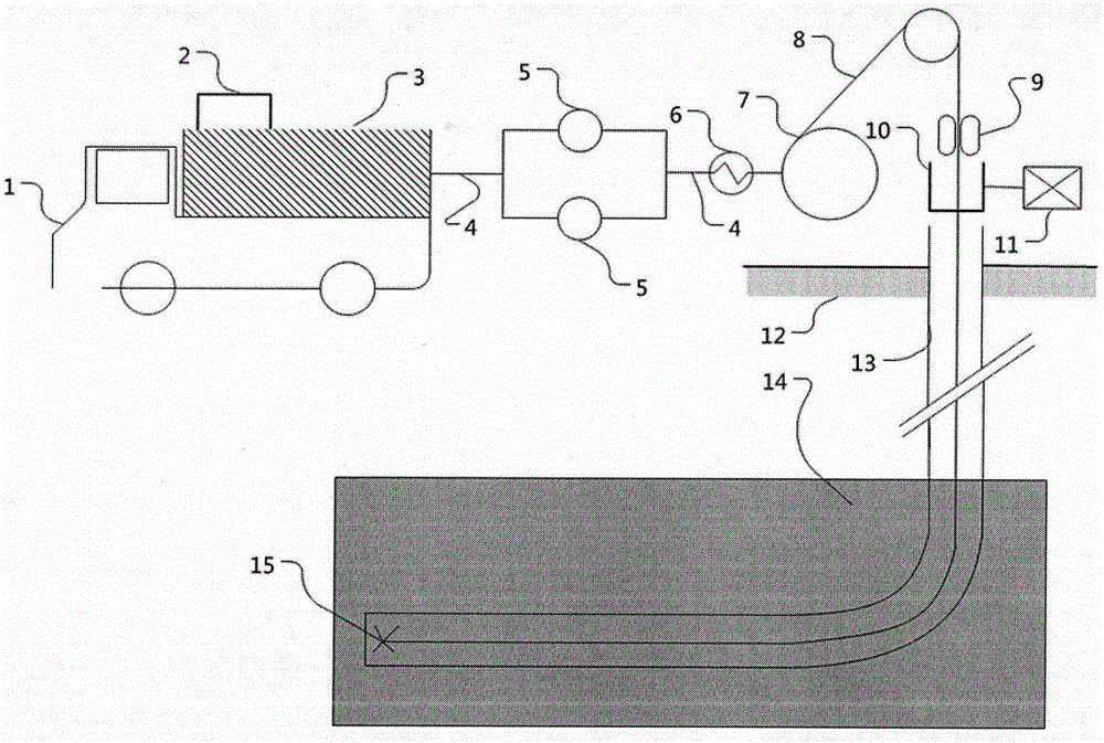
[0028] 1. Lower into the rotary jet device

[0029] figure 1 Shown is supercritical CO 2 Schematic diagram of the rotary jet device entering the well. Supercritical CO 2 The rotary jet device 15 is connected to the coiled tubing 8, passes through the coiled tubing injection head 9, the wellhead device 10 and the wellbore 13 are lowered into the bottom of the well.

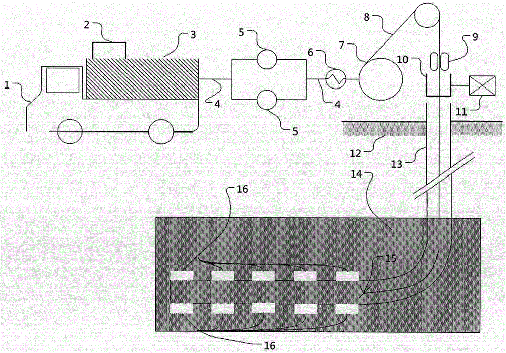
[0030] 2. Multi-stage reaming

[0031] figure 2 Shown is a schematic diagram of supercritical carbon dioxide rotating jet multi-stage reaming.

[0032] Liquid CO 2 By CO equipped with vehicle-mounted refrigerating unit 2 2 Tanker 1 transport, the transport pressure is controlled at 4-5MPa, and the temperature is controlled at -10°C-5°C.

[0033] CO 2 Liquid CO in storage tank 3 2 It is transp...


PUM


Abstract

The invention relates to a coalbed methane horizontal well supercritical CO2 jet flow cavity construction and multi-segment synchronous deflagration fracturing method. The method comprises the following steps: completing coalbed methane horizontal well drilling, introducing a coiled tubing into an supercritical CO2 rotary jet flow rock-breaking device to the bottommost end of a shaft, and performing pore broadening on the shaft by using an underground supercritical CO2 rotary jet flow rock-breaking device in order to form a cylindrical pore which is 1.0-1.5 meters in diameter and is 2-4 meters in length underground; after first-segment pore broadening is finished, lifting a rotary jet-flow tool to perform second-segment pore broadening work and so forth to finish pore broadening work of all well segments, wherein the segment distances are 80-100 meters; putting a solid explosive into a pore broadening cavity by using the coiled tubing after finishing pore broadening, and introducing a screen pipe; lastly, pressurizing by using a ground high-pressure CO2 pump to ignite the explosive, and mixing generated high-energy gas with a supercritical CO2 fracturing coalbed. By adopting the method, a plurality of complex volume cracks can be generated in the coalbed, explosive fracturing contributes to coalbed stress unloading after pore broadening, and the coal rock permeability can be improved effectively, so that the yield of a coalbed methane horizontal well is improved.

Description

technical field [0001] The invention relates to a coalbed gas well fracturing stimulation method, in particular to a coalbed gas horizontal well staged fracturing method, which belongs to the field of petroleum drilling. Background technique [0002] Hydraulic fracturing technology is currently the main application technology for coalbed methane stimulation. The commonly used fracturing fluid media are water-based fracturing fluid, gas energized (foam fracturing fluid) and alcohol-based fracturing fluid. The hydraulic fracturing technology is well developed and the process is relatively mature, but there are limitations in that the construction period is long, drainage is required, the equipment is complicated, the cost is high, and the coal seam is often polluted, and most of the cracks produced are single main cracks, and it is difficult to form a network of cracks. High-energy gas fracturing has also been applied in the development of coalbed methane. Explosion shock wave...

Claims


Application Information

Patent Timeline
Patent Type & Authority Applications(China)
IPC IPC(8): E21B7/18E21B7/28E21B43/263E21B43/16
CPCE21B7/18E21B7/28E21B43/006E21B43/164E21B43/263
Inventor 王海柱李根生刘庆岭田守嶒黄中伟沈忠厚
Owner CHINA UNIV OF PETROLEUM (BEIJING)
Why Eureka
Try Eureka