Runner rotating in radial direction due to end face stress and pressure power machine of runner

A power machine and the other end face technology, applied in the field of runners and pressure power machines, can solve the problems of low energy, large movement vibration, etc., and achieve the effects of low noise, uniform power transmission and stable work

Inactive Publication Date: 2016-06-01
江国兵
View PDF6 Cites 4 Cited by
  • Summary
  • Abstract
  • Description
  • Claims
  • Application Information

AI Technical Summary

Problems solved by technology

This kind of pneumatic power machine has: small energy, uniform power transmission part, large motion vibration

Method used


Image

  • Runner rotating in radial direction due to end face stress and pressure power machine of runner
  • Runner rotating in radial direction due to end face stress and pressure power machine of runner
  • Runner rotating in radial direction due to end face stress and pressure power machine of runner

Examples


Embodiment Construction

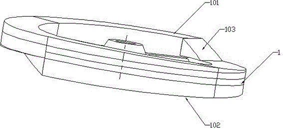
[0019] Such as figure 1 As shown, a runner whose end surface is forced to rotate radially includes a runner body 1, one end surface of the runner body 1 is provided with at least one first helical surface 101, and the other end surface of the runner body 1 is provided with at least one A second helicoid 102, the first helicoid 101 and the second helicoid 102 are arranged at an angle of 180°; the first and second helicoids 101, 102 are respectively provided with a section of transition slope 103 at the junction of the end and the end. The flywheel can also adopt a multi-helicoid structure, that is, when the number of the first helicoids is multiple, the multiple first helicoids are concentrically arranged; when the number of the second helicoids is multiple, the multiple second helicoids are concentrically arranged .

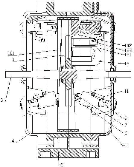
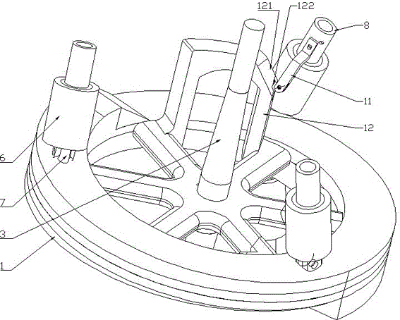
[0020] Such as figure 1 , image 3 , Figure 4 , Figure 5 and Figure 6 As shown, a pressure power machine using the above-mentioned runner includes a box...


PUM


Abstract

A runner rotating in the radial direction due to end face stress comprises a runner body. At least one first spiral face is arranged on one end face of the runner body, and at least one second spiral face is arranged on the other end face of the runner body. Two sections of transition inclined faces are arranged at the head-tail combining positions of the first spiral face and the second spiral face. A pressure power machine comprises a box, an output shaft and the runner. The runner is arranged on the output shaft. A front end cover and a rear end cover are arranged at the two ends of the box. A plurality of pressure cylinders are arranged on the inner side of the front end cover, and a plurality of pressure cylinders are arranged on the inner side of the rear end cover. The pressure cylinders are obliquely arranged relative to the axis of the output shaft. Bearings are arranged at the heads of piston rods of the pressure cylinders on the two sides, and the bearings on the two sides make contact with the first spiral face and the second spiral face. The input end of each pressure cylinder sequentially passes through a pressure control device and an input pipeline to be connected with a pressure supply device, wherein the pressure control device can control closing/opening of the input pipeline. Pressure is exerted on the spiral faces, the spiral faces convert pressure into rotating force, and then the runner can rotate.

Description

technical field [0001] The invention relates to a runner whose end face is radially rotated by force and a pressure power machine thereof. Background technique [0002] The existing runner drives the runner to rotate through the rotating fly output shaft, or the peripheral surface of the runner is forced to rotate, and there is no runner that realizes rotation through pressure. [0003] A power machine is a machine that converts energy such as heat or electricity into mechanical energy. Most of the existing power machines consume a lot of gasoline or diesel, such as internal combustion engines, and some power machines emit a large amount of exhaust gas, causing air pollution, or have low mechanical efficiency. The current pneumatic power machine includes a base, a self-closing switch assembly or a cylinder is installed on the base, a connecting rod is movably connected with the cam on the piston of the cylinder, and a transmission pulley is connected on the protruding output...

Claims


Application Information

Patent Timeline
Patent Type & Authority Applications(China)
IPC IPC(8): F01B3/04F01B3/10
CPCF01B3/04F01B3/103
Inventor 江国兵
Owner 江国兵
Why Eureka
Try Eureka