
Packing seal structure

A packing seal and packing ring technology, which is applied to shaft seals, valve details, engine components, etc., can solve problems such as insufficient stability, poor sealing performance, and poor sealing performance of valves, so as to eliminate valve problems and improve utilization. , Strengthen the sealing effect

Inactive Publication Date: 2016-06-01
王小勇
View PDF0 Cites 0 Cited by
  • Summary
  • Abstract
  • Description
  • Claims
  • Application Information

AI Technical Summary

Problems solved by technology

[0003] When the existing valve stem is in motion, the stability is insufficient, and a single packing is used for sealing, and the sealing performance is not strong, resulting in poor sealing performance of the entire valve

Method used


Image

  • Packing seal structure

Examples


Embodiment l

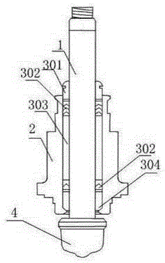
[0019] As shown in Figure 1, a packing sealing structure includes a valve body 2, a valve stem 1 arranged in the valve body 2, and a valve core 4 connected to the lower end of the valve stem 1, and is characterized in that it also includes a lower guide pipe 304, A lower packing ring 305 with 2~4 turns is arranged above the lower guide pipe 304, an intermediate sealing tube 303 is arranged above the lower packing ring 305, an upper packing ring 302 with 4~8 turns is arranged above the middle sealing pipe 303, and the upper packing ring 302 An upper guide pipe 301 is arranged above, and the upper guide pipe 301, the lower guide pipe 304, the lower packing ring 305, the upper packing ring 302 and the intermediate sealing pipe 303 are all sleeved on the valve stem and contacted in the valve body.

[0020] The setting of the upper and lower guide pipes can stabilize the valve stem from both ends, prevent excessive vibration of the valve stem, and enhance the stability of the valve ...

Embodiment 2

[0022] As shown in FIG. 1, both the lower packing ring 305 and the upper packing ring 302 are provided with a V-shaped layer or an O-shaped layer of polytetrafluoroethylene or perfluororubber. The outside of the V-shaped layer or the O-shaped layer of the lower packing ring 305 and the upper packing ring 302 is carburized polytetrafluoroethylene or polyether ether ketone.

[0023] The O-shaped sealing ring is low in cost, good in sealing performance, wide in application range, simple in structure and has a self-sealing effect, often only one seal can be used to complete the sealing, the sealing effect is good, and its sealing performance remains unchanged when used for reciprocating motion sealing. Medium leakage is very small. The V-shaped sealing ring is a lip-shaped sealing ring. In the free state, the outer diameter of the lip of the V-shaped sealing ring is larger than the inner diameter of the packing cavity, and the inner diameter of the lip is smaller than the outer di...


PUM


Abstract

The invention discloses a packing seal structure, which comprises a valve body, a valve rod and a valve core, wherein the valve rod is arranged in the valve body, and the valve core is connected with the lower end of the valve rod; the packing seal structure also comprises a lower guide tube; two to four circles of lower packing rings are arranged above the lower guide tube; a middle seal tube is arranged above the lower packing rings; four to eight circles of upper packing rings are arranged above the middle seal tube; an upper guide tube is arranged above the upper packing rings; and the upper guide tube, the lower guide tube, the lower packing rings, the upper packing rings and the middle seal tube separately sleeve the valve rod and are separately in contact with the interior of the valve body. According to the packing seal structure provided by the invention, movement stability of the valve rod can be enhanced, and a valve problem brought by guiding of a sleeve can be solved; moreover, sealing on the valve rod part can also be enhanced, and the service life of packing is prolonged.

Description

technical field [0001] The invention relates to a stuffing sealing system, in particular to a stuffing sealing structure used on a valve. Background technique [0002] Contact dynamic seals that rely on packing to block the leakage path and can be used for reciprocating or rotating motion mainly include soft packing seals and hard packing seals. The soft packing seal is also called the packing seal. The stuffing in the stuffing box is radially expanded and tightened by the axial force of the gland to achieve the purpose of sealing. Soft fillers are often composed of fibers (asbestos, nylon, etc.), lubricants (graphite, molybdenum disulfide, talcum powder, etc.) and various wire reinforcements. After the packing is worn, it can be compensated by tightening the bolts. The soft packing seal has a simple structure, reliability, easy maintenance, corrosion resistance and high temperature resistance, and has been widely used as a seal for rotating shafts and reciprocating rods, ...

Claims


Application Information

Patent Timeline
Patent Type & Authority Applications(China)
IPC IPC(8): F16K41/04F16K41/10
Inventor 王小勇
Owner 王小勇
Learn More