LED lamp filament assembly, method for forming LED lamp filament bulb and LED lamp filament bulb

A technology of LED filaments and components, applied in semiconductor devices of light-emitting elements, components of lighting devices, cooling/heating devices of lighting devices, etc., can solve the problem of reduced photoelectric conversion efficiency, low application power, and lack of replaceable standard light sources and other issues, to achieve the effect of improving the light extraction efficiency and increasing the heat radiation area

Active Publication Date: 2016-06-01
GUIZHOU GUANGPUSEN PHOTOELECTRIC
11 Cites 4 Cited by

AI-Extracted Technical Summary

Problems solved by technology

Although LED lighting has received attention, there are still many problems in the promotion process. First, LED lighting is mostly an integrated structure and lacks replaceable standard light sources. Realize dimming operation, and at the same time do not have waterproof and other protective functions, the application range is narrow; moreover, light-emitting semiconductors emit light from all sides under electrical triggering, but in practical applications, LED chips are mostly packaged in an opaque On the substrate, half of the light emitted by the semiconductor is blocked and converted into heat, resulting in low lumi...

Abstract

The invention discloses an LED lamp filament assembly, a method for forming an LED lamp filament bulb and the LED lamp filament bulb. The LED lamp filament assembly comprises one or more LED lamp filaments (1.1) with the two ends provided with electric connecting terminals (1.3). The electric connecting terminals (1.3) at the two ends of each LED lamp filament (1.1) are connected with two heat conduction and electricity conduction terminal supports (1.4). According to the LED lamp filament assembly, the light emitting rate of an LED can be increased, and the heat dissipation efficiency can be improved. According to the method for forming the LED lamp filament bulb and the LED lamp filament bulb, the limitation that an existing LED lighting lamp needs a radiator can be avoided, a large-power LED lamp filament lamp light source can be achieved, a light source of an existing large-power lighting product can be directly replaced, and lamps do not need to be replaced.

Application Domain

Technology Topic

Image

  • LED lamp filament assembly, method for forming LED lamp filament bulb and LED lamp filament bulb
  • LED lamp filament assembly, method for forming LED lamp filament bulb and LED lamp filament bulb
  • LED lamp filament assembly, method for forming LED lamp filament bulb and LED lamp filament bulb

Examples

  • Experimental program(1)

Example Embodiment

[0044] The present invention will be further described below in conjunction with the drawings and embodiments, but it is not a basis for limiting the present invention.
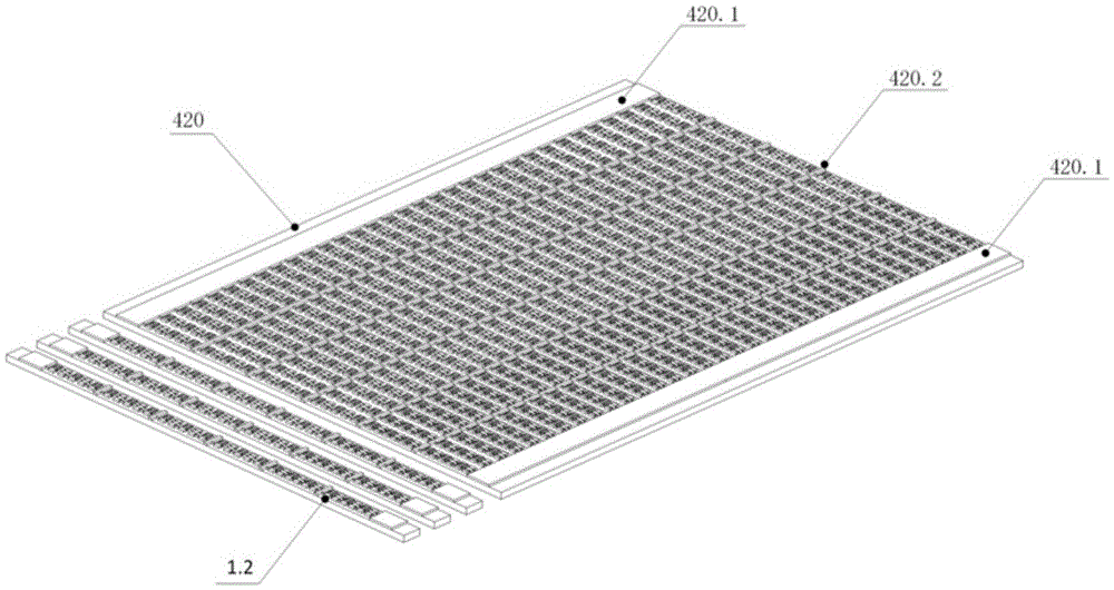
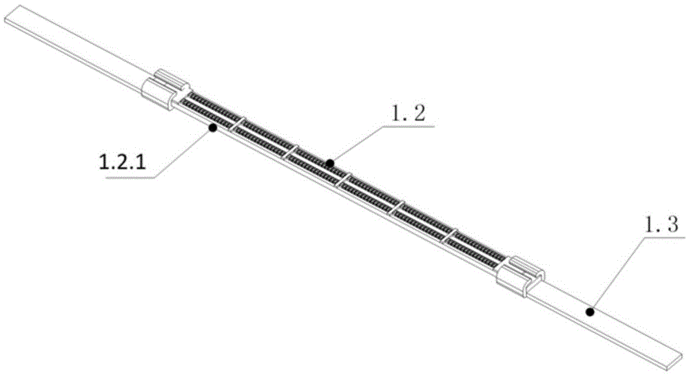
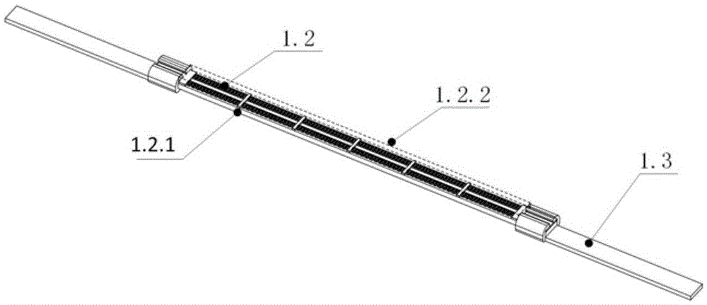
[0045] Examples. An LED filament assembly, such as Figure 4 with Figure 5 As shown, it includes one or more LED filament 1.1 with electrical connection terminals 1.3 at both ends, and the electrical connection terminals 1.3 at both ends of the LED filament 1.1 are respectively connected to two thermally conductive terminal brackets 1.4. The LED filament 1.1 includes an LED filament module 1.2 and electrical connection terminals 1.3 at both ends. The LED filament module 1.2 includes a strip or block filament module substrate 1.2.1 and a filament module substrate 1.2.1 on the LED chip series group, LED filament module 1.2 is provided with a transparent package. In order to facilitate heat transfer, the part of the electrical connection terminal 1.3 near the terminal bracket 1.4 can be appropriately widened or rounded, such as Image 6 As shown; in order to improve the light transmission effect, especially when used for planting industry lighting, the glass cover plate 1.2.2 package solution is adopted to form a block filament component solution, such as Figure 7 Shown.
[0046] The LED filament module 1.2 is cut by a large LED lighting chip 420 into a strip or block structure containing one or more rows of LED chip sets, such as figure 1 As shown; or, the LED filament module 1.2 is composed of a plurality of LED series groups or a plurality of parallel LED series groups encapsulated on the strip filament module substrate 1.2.1, the LED series group consists of a plurality of LED chips Or LEDPN junction is formed in series, such as figure 2 Shown.
[0047] Among them, the LED lighting chip is based on the inventor's previous application number of the LED lighting chip in the patent application 201410214077.9. The cut LED lighting chip contains one or more rows of LED chip sets according to the power; LED lighting The large chip is produced by direct crystal growth, and there is no gap connection between the light-emitting semiconductor material and the chip substrate. The LED lighting large chip substrate uses high-purity alumina (single crystal or polycrystalline) material and no metal on the back of the substrate The reflective layer can make the light generated by the semiconductor to the substrate directly penetrate the chip substrate and overflow to the outside, so that the chip heats up to a minimum; the LED lighting large chip substrate adopts single crystal silicon or single crystal silicon carbide material. When the chip heats up, the wavelength of the generated heat rays is within the infrared band, and the infrared wave can be directly emitted through single crystal silicon or single crystal silicon carbide, so that the chip has better thermal conductivity.
[0048] The method of using the aforementioned LED filament assembly to construct an LED filament bulb: the LED filament assembly 1 is arranged in the bulb shell 6 with the driving assembly 3 and the lamp cap assembly 2, and the LED filament assembly 1 is fixed on the wire bracket 4.1 through the electrical connection wire 4.2 Connected with the drive assembly 3 and the lamp cap assembly 2, the internal temperature of the bulb is controlled by controlling the area of ​​the heat radiator assembly in the bulb shell 6, and the average temperature on the heat radiator assembly approaches the chip junction temperature to balance the LED filament 1.1 The heat generated, wherein the heat radiator assembly includes an LED filament 1.1, a terminal bracket 1.4, a wire bracket 4.1 and an electrical connection wire 4.2.
[0049] When the LED power is greater, additional heat radiator components can be added, such as Figure 8 As shown, specifically, a heat radiation bracket 5.1 is provided on the connection terminal bracket 1.4, and a heat radiation ring 5.3 is also connected to the heat radiation bracket 5.1. The bulb shell 6 is filled with inert gas with high thermal conductivity to make the heat in the bulb shell 6 The temperature on the heat radiator assembly is balanced through conduction and convection, and at the same time part of the heat on the heat radiator assembly can be transferred to the bulb shell; the bulb shell 6 is blown into one body or divided into multiple sections of the same material or different materials The heat radiation bracket 5.1 and the heat radiation ring 5.3 are both close to the bulb shell 6, so that the heat generated by the LED filament 1.1 is conducted to the bulb shell 6, so that the heated bulb shell becomes an integral part of the heat radiator assembly, which assists in strengthening The heat radiation capability of the heat radiator component.
[0050] The surface of the heat radiator component that cannot reflect and cannot transmit heat rays, visible light waves and infrared light waves, is coated with black thermally conductive material. The best choice is superconducting graphite or graphene coating to form a radiant black body surface 5.32; it can reflect but cannot The side that transmits heat rays is set as a reflecting mirror 5.31.
[0051] The end of the LED filament assembly 1 is connected to other heat radiator components close to the bulb shell 6 through a heat pipe 7.16, so that the heat radiator components in the bulb shell 6 are rapidly uniformly heated. Such as Figure 13 , Picture 14 with 19 Shown.
[0052] The driving component can be a driving power supply manufactured based on the method of the inventor's application number 201410211945.8 and 201410214074.5 Chinese patent application, which divides the LED load into 1 to 6 segments to drive, and can obtain higher power efficiency (greater than 99%), only in this way when the power of the LED bulb is high, the drive power can be placed in the lamp head assembly, so that there will be no overheating and unstable power supply. Otherwise, when the power of the bulb is high, the lamp holder assembly cannot dissipate the heat emitted by the driving power supply; based on this power supply scheme, the LED bulb constructed by the present invention has a dimming function at low or no cost.
[0053] The lamp holder assembly includes a lamp holder 2.5 and an electrical connection end. The electrical connection end may be an electrical connector based on the inventor’s application number in the Chinese patent application of 201210253574.0. The electrical connector and the lamp holder 2.5 are integrated in a structure with the bulb shell. The connected lamp holder 2.5 adopts a threaded structure and is provided with a positioning slot 2.8. The positioning slot is set in the light direction of the bulb. The bulb is fixed on the lamp gimbal mounting interface bracket through a fixing nut 2.9; the drive assembly 3 is placed in the lamp holder 2.5. This brings a significant use effect. All lamp holder components based on the national standard type have a bare structure at the power connection end, which cannot be waterproof, and a waterproof design is required on the lamp. The structure of the present invention is simple and practical, so that the LED bulb has a waterproof function, so that the lamp does not need to be waterproof, and the cost of the lamp is greatly reduced. The type and size of the lamp holder assembly can be based on the GB/T1406 (1406.1 ~ 1406.5) series of standards, but for the lamp holder with 4-pin structure, if the rules are not changed, the 2 pins are defined as dimming signal access , That is, increase the signal pin V2-2.3 and signal pin V2+2.4; so that the entire bulb has a dimming function. When the signal level changes from 0 to 5VDC, the brightness of the bulb changes from maximum brightness to zero brightness. The brightness of the bulb can be controlled by light control, voice control, time control, infrared induction, etc., which is beneficial to apply the present invention to various places that need dimming, especially when used in planting or road lighting, to achieve high energy saving purpose.
[0054] Side emitting LED filament bulb with reflector, such as Figure 8 with Picture 9 Shown: comprising a light bulb housing 6 with a drive assembly 3 and a lamp cap assembly 2. The light bulb housing 6 is provided with an LED filament assembly 1, a wire holder 4.1, an electrical connection wire 4.2, a heat radiation holder 5.1 and a heat radiation ring 5.3; the LED The terminal brackets 1.4 at both ends of the filament assembly 1 are respectively connected to two parallel heat radiation brackets 5.1, and the heat radiation bracket 5.1 is provided with an arc structure close to the bulb shell 6; the heat radiation ring 5.3 is an unclosed cylindrical structure , And the two ends of the separation part are respectively connected with two heat radiation brackets 5.1, the inside of the heat radiation ring 5.3 is a reflecting mirror surface 5.31, and the outside is a radiation black body surface 5.32 close to the bulb shell 6; the LED filament assembly 1 is electrically connected The wire 4.2 is connected with the driving assembly 3 and the lamp cap assembly 2, and the electrical connection wire 4.2 is fixed by the wire bracket 4.1.
[0055] The separated end of the heat radiating ring 5.3 and the terminal bracket 1.4 are tightly connected together by the fixing bead 7.4 and the heat radiating bracket 5.1, and one of the ends of the separated heat radiating ring 5.3 and the terminal bracket 1.4 is connected to the terminal bracket 1.4. An insulating and thermally conductive spacer 7.5 is provided, and the insulating and thermally conductive spacer 7.5 is located between the terminal bracket 1.4 and the heat radiation ring 5.3. One end of the heat radiation ring and the heat radiation bracket are provided with an elliptical opening, which is fixed by a fixing screw 7.3, which is convenient to adjust the arc distance between the heat radiation ring and the bulb shell. The top and bottom of the cylindrical structure of the heat radiation ring 5.3 are respectively provided with an inner upper fixed cover 7.1 and an inner lower fixed cover 7.2, and the inner upper fixed cover 7.1 and the inner lower fixed cover 7.2 are closely attached to the bulb shell 6.
[0056] A plurality of parallel LED filament assemblies 1 are arranged between the two separate ends of the heat radiation ring 5.3. The adjacent LED filament assemblies 1 are connected by a fixed bead 7.4 and a heat radiation bracket 5.1, and the The heat radiation bracket 5.1 is provided with an arc structure close to the bulb shell 6. Such as Picture 9 , 8 , 9 and 10. When the lamp head assembly is a waterproof connector assembly, as shown in 12 and 13, the specific waterproof connector can be used Figure 16 The specific structure shown.
[0057] Down-emitting LED filament bulb with reflector, such as Figure 17 with 18 Shown: comprising a light bulb housing 6 with a drive assembly 3 and a lamp cap assembly 2. The light bulb housing 6 is provided with an LED filament assembly 1, a wire bracket 4.1, an electrical connection wire 4.2, a heat radiation bracket 5.1 and a heat radiation ring 5.3; The radiating ring 5.3 is a closed cylindrical structure. The inner side of the lower end of the cylindrical structure is a concave frustum-shaped thin shell structure. The LED filament assembly 1 is fixed in the frustum-shaped thin shell structure. The two terminal brackets 1.4 of the LED filament assembly 1 are respectively Connected to the upper and lower edges of the frustum-shaped thin shell structure; the outer side of the heat radiation ring 5.3 is close to the bulb shell 6, and the surface of the heat radiation ring 5.3 that cannot be irradiated by the light of the LED filament assembly 1 is the radiation black surface 5.32, The surface that can be irradiated by the light of the LED filament assembly 1 is a reflective mirror surface 5.31. The LED filament assembly 1 is connected to the driving assembly 3 and the lamp holder assembly 2 through an electrical connection wire 4.2, and the electrical connection wire 4.2 is fixed by a wire bracket 4.1. The two terminal brackets 1.4 of the LED filament assembly 1 are two ring structures with different sizes. The terminal bracket 1.4 with a small size is fixed to the edge of the frustum-shaped thin shell structure through a small ring fixing bead 7.4 with a small size. The fixed bead 7.4 is connected to the annular heat radiation support 5.11 through the heat pipe 7.16, and the annular heat radiation support 5.11 is connected to the heat radiation ring 5.3; the large terminal bracket 1.4 is connected to the lower edge of the frustum-shaped thin shell structure through the large annular fixed bead 7.4 A ring-shaped insulating and thermally conductive spacer 7.5 is provided between the small-sized terminal bracket 1.4 and the upper edge of the frustum-shaped thin shell structure; the ring-shaped fixed bead 7.4 and the ring-shaped heat radiation bracket 5.11 are located on the heat radiation ring 5.3 Inside the cylinder structure.

PUM

no PUM

Description & Claims & Application Information

We can also present the details of the Description, Claims and Application information to help users get a comprehensive understanding of the technical details of the patent, such as background art, summary of invention, brief description of drawings, description of embodiments, and other original content. On the other hand, users can also determine the specific scope of protection of the technology through the list of claims; as well as understand the changes in the life cycle of the technology with the presentation of the patent timeline. Login to view more.

Similar technology patents

Classification and recommendation of technical efficacy words

  • Improve light extraction efficiency
  • Large heat radiation area

GaN-based light emitting diode and preparation method thereof

InactiveCN101937953AImprove light extraction efficiencyAchieve Broad Spectral OutputSemiconductor devicesMultiple quantumBlocking layer
Owner:SUZHOU NANOJOIN PHOTONICS

Independently controllable high-temperature equipment provided with multiple vacuum cavities

InactiveCN106586282ALarge heat radiation areaShort vacuum timePackaging under vacuum/special atmosphereContainers for heating foodVacuum pumpingElectromagnetic valve
Owner:CHINA ELECTRONICS TECH GROUP CORP NO 16 INST

Drying heating method for production resumption of coke dry quenching furnace after medium repair

ActiveCN107201237ALarge heat radiation areaFast heatingCoke quenchingPush outQuenching
Owner:SHANGHAI MEISHAN IRON & STEEL CO LTD
Why Eureka
Try Eureka