Automatic gas stove oil fume adsorption method

A gas stove and oil fume technology, which is applied in the field of gas stoves, can solve problems such as high cost, and achieve the effects of reducing costs, ensuring safety, and reducing space occupation.

Inactive Publication Date: 2016-06-01
王丰利
View PDF0 Cites 2 Cited by
  • Summary
  • Abstract
  • Description
  • Claims
  • Application Information

AI Technical Summary

Problems solved by technology

[0004] The invention provides a method for automatically absorbing cooking fume by a gas stove, which solves the high co

Method used


Image

  • Automatic gas stove oil fume adsorption method
  • Automatic gas stove oil fume adsorption method

Examples


Embodiment 1

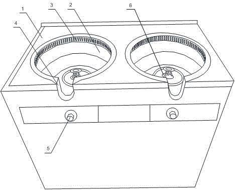
[0020] Such as figure 1 As shown, this embodiment includes a cooker body panel 1 and a burner. The middle part of the cooker body panel 1 is provided with a conical cavity 2 sunken downwards, and a U-shaped groove 4 is also opened on the cooker body panel 1. The cavity 2 communicates with the outside world through a U-shaped groove 4. The bottom of the cavity 2 is equipped with a burner, and also includes a plurality of smoking holes 3 and fans. within 1. The panel 1 of the cooker body adopts a conical cavity 2 sunken downwards. The cavity 2 is connected to the outside world through a U-shaped groove 4. The bottom of the cavity 2 is installed with a combustion system. Hole 3, place the pot at the bottom of the cavity 2 when in use, and the handle of the pot can be placed in the U-shaped groove 4. Under the adjustment of the switch 5, the combustion system starts to ignite, and the fan starts to absorb the generated smoke through the numerous smoking holes 3. so that the pres...

Embodiment 2

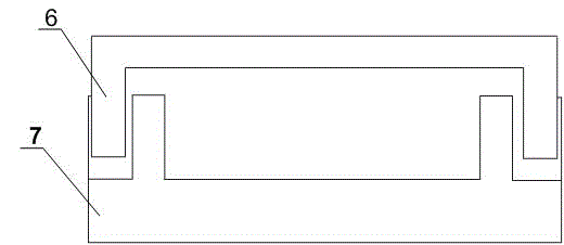
[0022] Such as figure 1 As shown, the present embodiment is based on Embodiment 1, because the cooker head panel 1 is connected to the burner, and the burner includes a burner head 7 and a fire cover 6, so a plurality of openings are provided at the bottom of the cavity 2, and the burner The head 7 is bolted to the bottom of the cavity body 2 through the opening, and the opening is turned up, and the height of the turning is greater than 2mm, so as to prevent overflowing liquid from flowing into the stove.

[0023] The top of the fire cover 6 is provided with a thermocouple type flameout protection device. When the control switch 5 button is ignited with a small fire, the thermocouple is heated by its flame to generate thermoelectric potential, which is introduced into the electromagnetic coil through the wire, and a magnetic field is generated to make the electromagnetic valve close, the gas valve opens, and the combustion path is opened to maintain its normal combustion ;On...


PUM


Abstract

The present invention discloses an automatic gas stove oil fume adsorption method. The gas stove comprises a stove body panel and a burner, wherein the middle portion of the stove body panel is provided with a chamber recessing downward and presenting a conical shape, the stove body panel is provided with a U-shaped groove, the chamber is communicated to the outside through the U-shaped groove, the bottom portion of the chamber is provided with the burner, a plurality of oil fume adsorption holes and a fan are arranged, the oil fume adsorption holes are distributed on the inner wall of the chamber in an annular array manner, and the fan is arranged inside the stove body panel. According to the present invention, the chamber recessing downward and presenting the conical shape is arranged on the stove body panel, and is communicated to the outside through the U-shaped groove, the bottom portion of the chamber is provided with the burning system, and the plurality of the oil fume adsorption holes are arranged on the upper edge of the inner wall of the chamber; during the use, the pot is placed on the bottom portion of the chamber, the pot handle can be placed inside the U-shaped groove, the burning system starts strike fire under the adjustment of the switch, and the fan starts the adsorption of the generated oil fume through the plurality of the oil fume adsorption holes; and the arrangement of the separate oil fume exhaust ventilator on the gas stove is eliminated, such that the occupation space is reduced, and the cost is reduced.

Description

technical field [0001] The invention relates to a gas cooker, in particular to a method for automatically absorbing oil fume by a gas cooker. Background technique [0002] Household gas stoves are generally composed of a gas supply system, a combustion system, a control system, an ignition system and other components. The gas supply system of the gas stove includes the gas inlet pipe, the gas delivery pipeline composed of the inlet pipe joint and the gas pipe, and the gas valve, etc., which have strict requirements on the airtightness of the gas; the control system mainly refers to the flameout safety protection device and the timing flameout device , they mainly play the role of safety protection for the use of gas stoves; the combustion system mainly refers to the burner, the gas is ejected from the nozzle, and after being ejected by the ejector, the surrounding air is introduced into the mixing tube for full mixing, and the air is adjusted The plate adjusts the size of t...

Claims


Application Information

Patent Timeline
IPC IPC(8): F24C15/20
Inventor 王丰利
Owner 王丰利
Why Eureka
Try Eureka