Offset measurement method and device and component alignment method and device

A measurement method and technology of a measurement device, applied in the direction of measurement devices, optical devices, instruments, etc., can solve the problems of low offset measurement accuracy and low alignment accuracy of parts to be aligned, and achieve accurate calculation, high precision, The effect of precise alignment

Inactive Publication Date: 2016-06-01
POLAR LIGHT TECH CO LTD
View PDF3 Cites 2 Cited by
  • Summary
  • Abstract
  • Description
  • Claims
  • Application Information

AI Technical Summary

Problems solved by technology

[0004] Therefore, the technical problem to be solved by the present invention is that the offset measure...

Method used


Image

  • Offset measurement method and device and component alignment method and device
  • Offset measurement method and device and component alignment method and device
  • Offset measurement method and device and component alignment method and device

Examples


Embodiment 1

[0051] This embodiment provides a method for measuring offset, which can be used, for example, to measure the offset between various components in a circuit board electrical testing system. The above-mentioned circuit board electrical testing system can include a detection head device, a camera, Fixtures, workpieces and other components, the camera is fixed on the detection head device, the fixture is installed on the detection head device, and the workpiece is loaded on the transport table, so there are offsets between the detection head device and the camera, fixture and workpiece quantity. For the detection head device itself, there is also an offset between the upper detection contact head and the lower detection contact head included in the detection head device. The above-mentioned offset measurement method can be applied to measure the offset between the detection head device and the camera, fixture and workpiece respectively, and can also be applied to measure the offs...

Embodiment 2

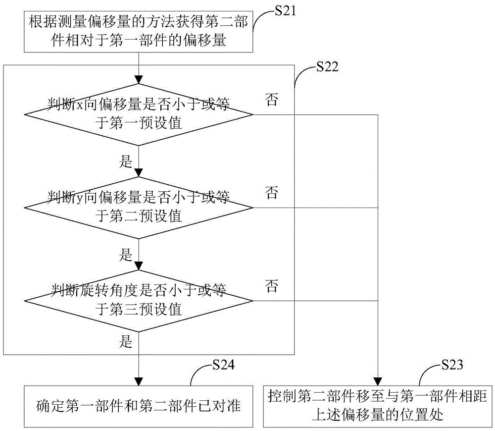
[0064] This embodiment provides a component alignment method, such as image 3 shown, including the following steps:

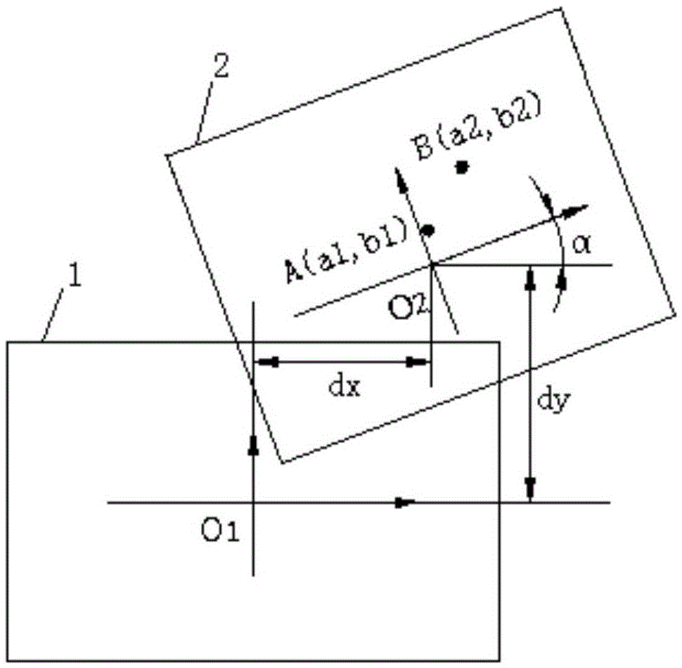
[0065] S21. Obtain the offset of the second component 2 relative to the first component 1 according to the offset measurement method of Embodiment 1, and the offset includes an x-axis offset dx, a y-axis offset dy, and a rotation angle α.

[0066] S22. Determine whether the x-direction offset dx is less than or equal to the first preset value, whether the y-direction offset dy is less than or equal to the second preset value, and whether the rotation angle α is less than or equal to the third preset value; When the x-direction offset dx is greater than the first preset value, the y-direction offset dy is greater than the second preset value or the rotation angle α is greater than the third preset value, enter step S23; when the x-direction offset dx is less than or When it is equal to the first preset value, the y-direction offset dy is less than or equal to ...

Embodiment 3

[0074] Corresponding to Embodiment 1, this embodiment provides an offset measurement device, such as Figure 4 shown, including:

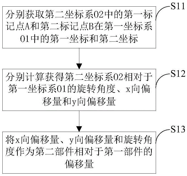
[0075] Marking point acquisition unit 11, used to respectively acquire the first coordinates ( x1, y1) and the second coordinates (x2, y2), where the first coordinate system O1 is the plane rectangular coordinate system where the first component is located, the second coordinate system O2 is the plane rectangular coordinate system where the second component is located, and the first coordinate system The planes where the system O1 and the second coordinate system O2 are located are parallel to each other;

[0076] The calculation unit 12 is used to calculate and obtain the rotation angle α, the x-direction offset dx and the y-direction offset dy of the second coordinate system O2 relative to the first coordinate system O1, respectively;

[0077] The offset obtaining unit 13 is configured to use the x-direction offset dx, the y-direction offset dy...


PUM


Abstract

The invention discloses an offset measurement method and device and a component alignment method and device. The offset measurement method comprises the steps that first coordinates and second coordinates in a first coordinate system O1 of a first mark point A and a second mark point B in a second coordinate system O2 are respectively acquired; the rotation angle alpha, x-direction offset dx and y-direction offset dy of the second coordinate system O2 relative to the first coordinate system O1 are respectively acquired through calculation; and the x-direction offset dx, the y-direction offset dy and the rotation angle alpha act as offset of a second component relative to a first component. The offset measurement method and device have the advantages of high measurement precision, and alignment of the first component and the second component is realized by using the offset measurement method so that alignment precision can be enhanced.

Description

technical field [0001] The invention relates to the technical field of electrical testing of printed circuit boards, in particular to an offset measurement method and device, and a component alignment method and device. Background technique [0002] At present, in order to reduce the test cost and improve the test efficiency when testing ordinary PCB circuit boards, special-purpose test machines are usually used for electrical testing. The testing principle of this testing machine is to first make a test fixture according to the design data of the PCB circuit board, and distribute a plurality of test probes on the fixture according to the position of the pad of the PCB circuit board. One-to-one correspondence between disks, that is, the workpiece (PCB circuit board to be tested) is fixed on the fixture during the test, and each test probe of the fixture contacts the corresponding pad on the PCB circuit board. The tester applies a constant current or Constant voltage or high...

Claims


Application Information

Patent Timeline
IPC IPC(8): G01B11/00
CPCG01B11/005G01B11/007
Inventor 覃早才
Owner POLAR LIGHT TECH CO LTD
Why Eureka
Try Eureka