Oscilloscope sampling and imaging system

An imaging system and oscilloscope technology, applied in the field of signal processing, can solve the problem of high dropout rate and achieve the effect of reducing the dropout rate

Inactive Publication Date: 2016-06-01
JIANGSU LVYANG ELECTRONICS INSTR GROUP
View PDF5 Cites 4 Cited by
  • Summary
  • Abstract
  • Description
  • Claims
  • Application Information

AI Technical Summary

Problems solved by technology

[0002] With the rapid development of science and technology, it is difficult for current digital phosphor oscilloscopes to completely capture, test and analyze high-speed and large-capacity data, modulated signals, long-frame digital communication signals composed of high-speed pulses, and other complicated signals, and the loss rate is relatively high.

Method used


Image

  • Oscilloscope sampling and imaging system

Examples


Embodiment Construction

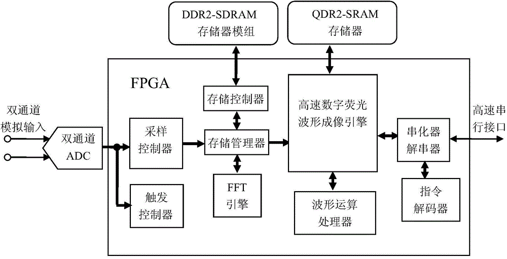
[0008] The oscilloscope sampling and imaging system of the present invention includes a dual-channel ADC, a DDR2-SDRAM memory module, a QDR2-SRAM memory, and an FPGA, and the dual-channel ADC, a DDR2-SDRAM memory module, and a QDR2-SRAM memory are respectively connected to the FPGA, wherein the dual The channel ADC receives the signal input from the analog front end and converts it into a digital signal; the FPGA implements all signal processing from digital signal input to waveform imaging transmission. All related algorithms are realized in FPGA. Each sampling and imaging module can realize signal acquisition, storage management and waveform imaging of two channels. The block diagram of this part is shown in Figure 1.

[0009] The ADC receives the signal input from the analog front end and converts it into a digital signal. To achieve the highest sampling rate and bandwidth, ADC selection is critical. The EV8AQXXX ADC produced by E2V Company is selected here. The amplitud...


PUM


Abstract

The invention belongs to the field of signal processing, and particularly relates to oscilloscope sampling and imaging module technology. An oscilloscope sampling and imaging system comprises the components of a double-channel ADC, a DDR2-SDRAM memory module, a QDR2-SRAM memory and an FPGA. The double-channel ADC, the DDR2-SDRAM memory module and the QDR2-SRAM memory are connected with the FPGA, wherein the double-channel ADC receives and simulates frontend signal input and converts the input signal to a digital signal. The FPGA realizes all signal processing operations from digital signal input to waveform imaging transmission. Through sampling signal data, a complicated signal is wholly captured and analyzed in higher precision and waveform visualizing of the data is performed, thereby displaying signal amplitude, time and frequency of the amplitude along with time on a screen, and effectively reducing loss rate.

Description

technical field [0001] The invention belongs to the field of signal processing, in particular to an oscilloscope sampling and imaging module technology. Background technique [0002] With the rapid development of science and technology, it is difficult for current digital phosphor oscilloscopes to completely capture, test and analyze high-speed and large-capacity data, modulated signals, long-frame digital communication signals composed of high-speed pulses, and other complicated signals, and the loss rate is relatively high. Contents of the invention [0003] The technical effects of the present invention can overcome the above defects, and provide an oscilloscope sampling and imaging system, which can better complete the analysis of signal data and effectively reduce the leakage rate. [0004] In order to achieve the above object, the present invention adopts the following technical scheme: it comprises dual-channel ADC, DDR2-SDRAM memory module, QDR2-SRAM memory and FPG...

Claims


Application Information

Patent Timeline
Patent Type & Authority Applications(China)
IPC IPC(8): G01R13/02
Inventor 刘礼伟宋云衢
Owner JIANGSU LVYANG ELECTRONICS INSTR GROUP
Why Eureka
Try Eureka