Output short-circuit protection method and circuit

A technology for output short circuit and circuit protection, applied in the direction of output power conversion devices, electrical components, etc., can solve the problems of poor anti-interference ability, poor reliability, misjudgment of the controller, etc., and achieve strong anti-interference ability, high reliability, The effect of filtering out noise interference

Active Publication Date: 2016-06-01
SHENZHEN NANYUN MICROELECTRONICS CO LTD
View PDF5 Cites 12 Cited by
  • Summary
  • Abstract
  • Description
  • Claims
  • Application Information

AI Technical Summary

Problems solved by technology

[0005] 1. The controller that uses the FB pin as the output short-circuit protection function, when designing a high-power power supply, there is a risk that the power tube on the primary side will be under large stress and the rectifier diode on the secondary side will be under high stress, which may cause it to burn out;
[0006] 2. The controller that uses the CS pin as the output short-circuit protection function, the CS pin is easily affected by the signal from the external interference noise source, causing the controller to misjudge, and its anti-interference ability and reliability are poor

Method used


Image

  • Output short-circuit protection method and circuit
  • Output short-circuit protection method and circuit
  • Output short-circuit protection method and circuit

Examples


Embodiment 1

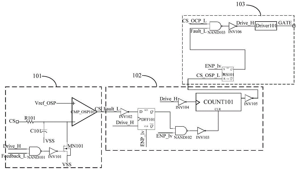
[0028] Such as figure 2 Shown is the schematic circuit diagram of Embodiment 1 of the present invention, an output short-circuit protection circuit, including: an overvoltage comparison unit 101 , a continuous comparison unit 102 , and a drive output unit 103 . Wherein, the continuous comparison unit 102 is a timing unit.

[0029] The overvoltage comparison unit 101 includes: a CS overvoltage comparator CMP_OSP101, a resistor R101, a capacitor C101, an N-channel MOS transistor MN101, an invertor INV101 and a NAND gate NAND101. The non-inverting input terminal of the CS overvoltage comparator CMP_OSP101 is connected to the internal comparison reference Vref_OSP of the controller, the current detection pin of the controller, namely the CS terminal, is connected to one end of the resistor R101, and the other end of the resistor R101 is connected to the positive plate of the capacitor C101, N The drain of the channel MOS transistor MN101 is connected to the negative input termin...

Embodiment 2

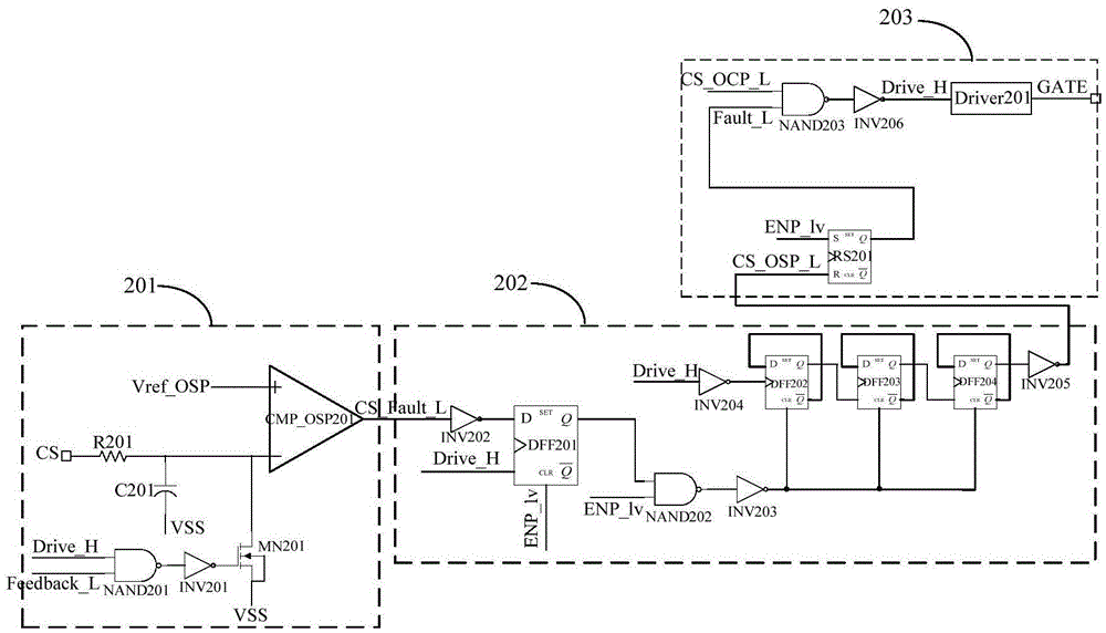
[0034] Such as image 3 As shown, compared with Embodiment 1, the difference is that the continuous comparison unit 202 is a counting unit. Specifically, the counter COUNT201 in the continuous comparison unit 202 is composed of three cascaded D flip-flops. The overvoltage comparison unit 201, the drive The output unit 203 is the same as the first embodiment, only the unit numbers are changed to 201 and 203 to distinguish them, which will not be repeated here.

[0035] The counter COUNT201 includes: D flip-flop DFF202, D flip-flop DFF203 and D flip-flop DFF204, D flip-flop DFF202, D flip-flop DFF203, and D flip-flop DFF204 are connected together, and the data receiving end of D flip-flop DFF202 D and its output Connected, the trigger input terminal of D flip-flop DFF202 is used as the input terminal of the counter, and is used to connect with the output terminal of NOT gate INV204 to access the low-voltage drive signal Drive_H; the output terminal Q of D flip-flop DFF202 is t...


PUM


Abstract

An output short-circuit protection method is disclosed. The method comprises the steps of generating a low-level effective CS-Fault-L signal when a preprocessed CS port voltage detected by an overcurrent comparator is higher than a CS overvoltage threshold value Vref-OSP set in a controller; detecting the CS-Fault-L signal in each period; if the detected CS-Fault-L signal is always in low level detected in continuous several periods, transmitting the low-level signal to a logic module; enabling a low-voltage driving signal Drive-H of a driving tube to be low level and transmitting the low-level Drive-H signal to a driving module; enabling a grid electrode driving signal GATE of an output power tube to be low level, switching off the power tube and finishing the protection function. Compared with the prior art, the output short-circuit protection method can remove noise interference by filtration and avoid wrong switch-off of the controller; and meanwhile, the output short-circuit protection method is high in anti-interference capability and reliability, and capable of ensuring that the current stress applied to the power tube and a secondary side diode cannot damage the power tube and the secondary side diode within a timekeeping range, so that the output short-circuit protection method can be applied to a high-power switching power supply.

Description

technical field [0001] The invention relates to a switching power supply, in particular to an output short-circuit protection method and circuit of a switching power supply. Background technique [0002] Most of the current switching power supply control chips integrate some protection functions, such as output over-voltage protection, over-power protection, open-loop protection, output short-circuit protection and other common switching power supply protection functions. figure 1 It is a commonly used flyback switching power supply with feedback control on the secondary side. If the output short circuit occurs on the secondary side, the output current will increase greatly, causing the switching power supply itself to burn out due to excessive power consumption. Therefore, in order to solve the problem of output short circuit , Usually the controller has an output short-circuit protection function inside the controller. An existing controller, such as Fairchild's PWM contr...

Claims


Application Information

Patent Timeline
Patent Type & Authority Applications(China)
IPC IPC(8): H02M1/32H02M1/44
CPCH02M1/32H02M1/44
Inventor 赵志伟唐盛斌
Owner SHENZHEN NANYUN MICROELECTRONICS CO LTD
Why Eureka
Try Eureka