
Liquid cooling system for avionic device

A kind of avionics equipment, liquid cooling technology, applied in the direction of cooling/ventilation/heating transformation, etc., can solve the problems of increasing aircraft compensatory loss, affecting aircraft aerodynamic shape, etc., to achieve the reduction of compensatory loss, simple structure, and thermal energy optimization Effect

Inactive Publication Date: 2016-06-01
XIAN AIRCRAFT DESIGN INST OF AVIATION IND OF CHINA
View PDF3 Cites 2 Cited by
  • Summary
  • Abstract
  • Description
  • Claims
  • Application Information

AI Technical Summary

Problems solved by technology

This temperature adjustment method still requires a certain amount of ram air, which also affects the aerodynamic shape of the aircraft and increases the compensatory loss of the aircraft.

Method used


Image

  • Liquid cooling system for avionic device

Examples


Embodiment Construction

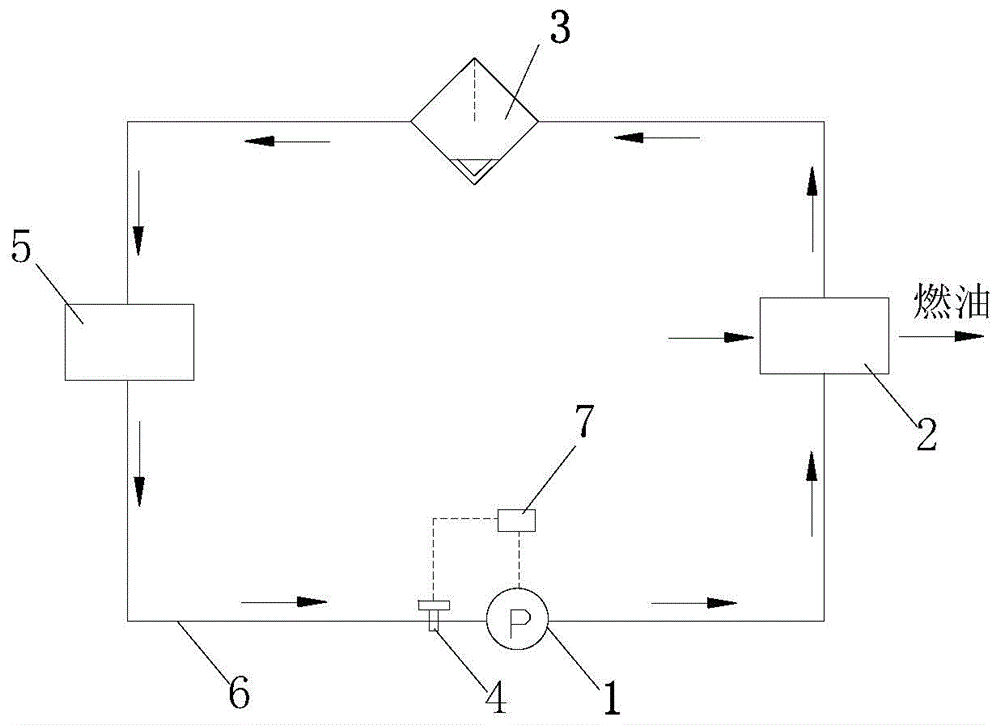
[0012] see figure 1 , the liquid pump 1, the liquid-liquid radiator 2, the gas-liquid separator 3 and the electronic equipment 5 are connected in sequence through the pipeline 6, and the temperature sensor 4 is arranged on the conduit downstream of the electronic equipment 5, and the controller 7 is connected with the electronic equipment 5 through the control line. The temperature sensor 4 is connected to the liquid pump 1 .

[0013] A closed liquid circulation cooling system is adopted. The liquid pump 1 provides circulation power for the flow of the coolant in the system pipeline 6. The coolant passes through the cold plate to take away the heat generated by the electronic equipment 5, and then enters the liquid-liquid radiator 2 to be fueled. Cooling, the gas-liquid separator 3 set in the system also functions as a gas-liquid separator and an expansion tank. The controller 7 can automatically adjust the speed of the liquid pump 1 according to the liquid temperature measure...


PUM


Abstract

The invention relates to a liquid cooling system for an avionic device, and the system is sequentially connected with a liquid pump (1), a liquid-liquid heat radiator (2), a gas-liquid separator (3) and electronic equipment (5) through a pipe (6). A conduit at the downstream side of the electronic equipment (5) is provided with a temperature sensor (4), and a controller (7) is enabled to be connected with the temperature sensor (4) and the liquid pump (1) through a control line. The gas-liquid separator (3) is disposed at the upstream side of the liquid pump (1). Compared with the prior art, the system is simple in construction, is stable and reliable in operation, does not need to punch an air inlet, and does not affect the pneumatic shape of an airplane. A conventional fuel oil system of an airplane serves as a heat sink, and the heat sink carries out heat exchange with the cooling liquid, thereby bringing away the heat generated by airborne electronic equipment. Meanwhile, a variable-frequency liquid pump is employed, and the rotating speed of the pump is automatically adjusted according to the liquid temperature of a pump inlet, so as to control the liquid supply temperature of the system, thereby achieving the optimal management of heat energy, and reducing the cost and loss of the airplane.

Description

technical field [0001] The invention belongs to the design technology of an aircraft environment control system. Background technique [0002] At present, most liquid cooling systems for high-power, high-heat-flux airborne electronic equipment use cooling liquid to take away the heat load of electronic equipment, and then use ram air to take the heat out of the machine. This cooling method requires a large amount of ram air to exchange heat with the coolant, and a ram air inlet needs to be opened on the fuselage, which seriously affects the aerodynamic shape of the aircraft and increases the compensatory loss of the aircraft. [0003] At the same time, there are generally two ways to control the liquid supply temperature of the system: ① by adjusting the opening of the electric damper to adjust the flow of ram air on the cold side to control the liquid supply temperature of the system. The structural strength requirements are high, and it has a great impact on the compensat...

Claims


Application Information

Patent Timeline
Patent Type & Authority Applications(China)
IPC IPC(8): H05K7/20
Inventor 李秦岭
Owner XIAN AIRCRAFT DESIGN INST OF AVIATION IND OF CHINA
Learn More