A magnetic ball mill for magnetite

A ball mill and magnetite technology, applied in grain processing and other directions, can solve the problems affecting the continuous operation of the ball mill, increase the load of the ball mill, increase the power consumption of the ball mill, etc., and achieve the effects of improving the grinding efficiency, increasing the effective collision, and having a simple structure.

Inactive Publication Date: 2017-11-10
WUHAN UNIV OF SCI & TECH
View PDF2 Cites 0 Cited by
  • Summary
  • Abstract
  • Description
  • Claims
  • Application Information

AI Technical Summary

Problems solved by technology

However, since the magnetic material is attached to the surroundings of the ball mill, it is not easy to discharge, and it is easy to cause blockage inside the ball mill, which affects the continuous operation of the ball mill. A large number of magnetic pole groups are located around the ball mill, which increases the load of the ball mill and increases the power consumption of the ball mill.

Method used


Image

  • A magnetic ball mill for magnetite
  • A magnetic ball mill for magnetite
  • A magnetic ball mill for magnetite

Examples


Embodiment 1

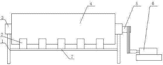
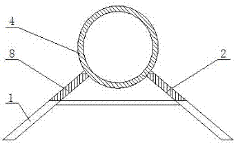
[0029] A magnetic ball mill for magnetite. Such as figure 1 and figure 2 As shown, the ball mill includes a support 1 , a first row of magnetic coils 2 , a second row of magnetic coils 8 , a cylindrical barrel 4 , a hollow shaft 5 and a programmable constant current source 9 . The two ends of the cylindrical body 4 are coaxially fixed with a hollow shaft 5, and the hollow shafts 5 at both ends are movably connected to the corresponding bracket 1 through their respective bearings 3, and one end of the hollow shaft 5 passes through the bracket 1 and is connected to the motor 6 through a belt. . The first row of magnetic coils 2 and the second row of magnetic coils 8 are correspondingly arranged on both sides of the vertical center line of the cylindrical shell 4, and the lower ends of the first row of magnetic coils 2 and the second row of magnetic coils 8 are evenly fixed on the On the corresponding horizontal beam 7, the upper ends of the first row of magnetic coils 2 and ...

Embodiment 2

[0040]A magnetic ball mill for magnetite. Except following technical parameter, all the other are with embodiment 1:

[0041] There are 6-10 magnetic coils 2 in the first row and 8 in the second row.

[0042] Compared with the prior art, this specific embodiment has the following positive effects:

[0043] 1. The first row of magnetic coils 2 and the second row of magnetic coils 8 are correspondingly arranged on both sides of the vertical centerline of the cylindrical body 4, and the lower ends of the first row of magnetic coils and the second row of magnetic coils 8 are evenly fixed On the corresponding horizontal beam 7, the upper ends of the first row of magnetic coils 2 and the second row of magnetic coils 8 are close to the cylindrical shell 4, and the first row of magnetic coils 2 and the second row of magnetic coils 8 are arranged symmetrically, both of which are 5~ 10 magnetic coils. Compared with the "ball mill magnetic liner" CN 102806123 A patent technology, the ...


PUM


Abstract

The invention involves a magnetic ball mill for magnetite.Its technical solution is: the first row of magnetic coils (2) on one side of the vertical center line of the cylindrical cylinder (4), and the lower end of the first row of magnetic coils (2) is evenly fixed at the horizontal beam (7)Upper, the upper end is close to the cylindrical cylinder (4), the first row of magnetic coils (2) are 5 ~ 10, the first row of magnetic coils (2) and the second row of magnetic coils (8) symmetrical settings, each magnetic coilThe central line is extended to the radius of the cylindrical cylindrical (4), respectively.Sub -control Hengli source (9) and each magnetic coil in the first row of magnetic coils (2) and the second row of magnetic coils (8) are connected in parallel, and the program control the constant current source (9) is equipped with a current control program.The polarity of the first row of magnetic coils (2) and the second row of magnetic coils (8) is the opposite.The polarity of each magnetic coil in the second row of magnetic coils (8) is the same.The present invention has the advantages of simple structure, convenient use, protecting lining, sorting, continuous operation and abrasion efficiency.

Description

technical field [0001] The invention belongs to the technical field of ball mills. In particular, it relates to a magnetic ball mill for magnetite. Background technique [0002] The ball mill is an important ore grinding equipment in the iron ore concentrator, and the iron ore ground by the ball mill is used for subsequent beneficiation operations. The iron ore in the ball mill achieves the purpose of grinding through impact and friction with steel balls. During the working process of the ball mill, the grinding efficiency is directly proportional to the falling speed of the steel balls; during the grinding process, the ore slurry is evenly distributed inside the ball mill, and the effective collision between the steel balls is not high. In addition, the traditional ball mill does not have the functions of protective liner and pre-sorting. [0003] "A permanent magnet ball mill" (CN 202336366 U) patented technology, which includes a cylinder and a motor, the outer surface...

Claims


Application Information

Patent Timeline
Patent Type & Authority Patents(China)
IPC IPC(8): B02C17/10B02C17/18B02C25/00
CPCB02C17/10B02C17/1805B02C25/00
Inventor 钱功明刘威刘露露张博
Owner WUHAN UNIV OF SCI & TECH
Why Eureka
Try Eureka