
Spot welding technological method for aluminum alloy workpiece

A process method, aluminum alloy technology, applied in metal processing equipment, manufacturing tools, welding equipment, etc., can solve the problems of large fluctuation of nugget diameter, large resistivity, easy to produce splash and splash, etc.

Active Publication Date: 2016-06-08
NANJING ENIGMA IND AUTOMATION TECH CO LTD
View PDF8 Cites 4 Cited by
  • Summary
  • Abstract
  • Description
  • Claims
  • Application Information

AI Technical Summary

Problems solved by technology

[0002] The aluminum element is very active, and it is very easy to form an oxide film on the surface of the aluminum alloy material. This layer of oxide film has a dense structure, a high melting point, and extremely poor electrical conductivity. It is prone to splashing and splashing, which is easy to cause harm to personnel.
Aluminum and copper alloys are easy to form a low melting point (547°C) eutectic, and the resistivity of this low melting point eutectic is relatively large, and the large heat generation on the contact surface causes local melting on the contact surface between the electrode and the workpiece, and A relatively violent eutectic reaction occurs, so that the adhesion between the electrode and the workpiece occurs, which deteriorates the surface quality of the solder joint
2. The local melting, splashing and adhesion of the electrode and the workpiece on the contact surface of the electrode and the workpiece destroy the continuity of the electrode surface
In the process of continuous spot welding, the discontinuity of the electrode surface has strong randomness, which makes the contact state between the electrode and the workpiece and between the workpieces very unstable.
In addition, affected by the surface state of the workpiece, electrode pressure, welding current and other factors, the nugget diameter fluctuates greatly in continuous spot welding

Method used


Image

  • Spot welding technological method for aluminum alloy workpiece
  • Spot welding technological method for aluminum alloy workpiece

Examples


Embodiment Construction

[0015] The technical solutions of the present invention will be described in detail below in conjunction with the accompanying drawings and embodiments.

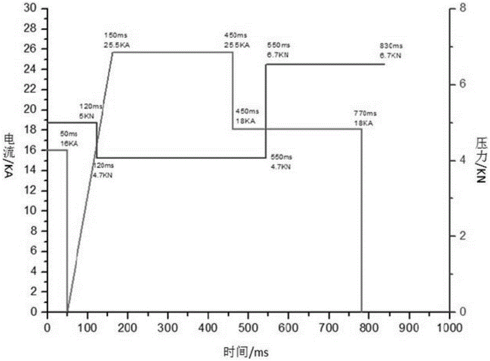
[0016] like figure 1 Shown, the spot welding process method of aluminum alloy workpiece of the present invention comprises following operation method:

[0017] Step 1. Pretreatment of the aluminum alloy workpiece to be spot welded: Since there is an oxide film on the surface of the aluminum alloy workpiece, it is necessary to pretreat the aluminum alloy workpiece:

[0018] First, place the workpiece to be welded in a sodium hydroxide solution with a concentration of 5% to 10% by mass and soak for 30 to 60 seconds for degreasing and rinsing; then place the workpiece to be welded in nitric acid with a concentration of 15% by mass Corrosion in the solution for 2 minutes, in order to slow down the growth rate of the new film and fill the pores of the new film, it can also be purified while corroding. The purification agent is p...


PUM

PropertyMeasurementUnit
diameteraaaaaaaaaa
shear loadaaaaaaaaaa

Abstract

The invention discloses a spot welding technological method for an aluminum alloy workpiece. The spot welding technological method comprises the following steps: pretreating the aluminum alloy workpiece to be subjected to spot welding; welding the pretreated aluminum alloy workpiece under the current of 15.2 KA and the pressure of 5.0 KN for 120 ms; then adjusting the welding current to 25.5 KA and the welding pressure to 4.2 KN, and welding the workpiece under the current and the pressure for 430 ms; further adjusting the welding current to 18 KA and the pressure to 6.7 KN, and welding the workpiece under the current and the pressure for 280 ms; naturally cooling the welded workpiece in air. According to the method disclosed by the invention, no splashing is generated in the welding process, and the diameter of a welded nugget can be greater than or equal to 6 mm, and the shear strength of the nugget is 0 to 5.4 KN; the surface hardness of the nugget is 0 to 50 HV; no obvious indentions are formed on the surface of the welded workpiece, and the offset of the nugget is extremely small (0 micron to 1 mm).

Description

technical field [0001] The invention relates to a spot welding process for an aluminum alloy workpiece, belonging to the field of welding technology. Background technique [0002] The aluminum element is very active, and it is very easy to form an oxide film on the surface of the aluminum alloy material. This layer of oxide film has a dense structure, a high melting point, and extremely poor electrical conductivity. It is prone to splashing and splashing, and it is easy to cause harm to personnel. Aluminum and copper alloys are easy to form a low melting point (547°C) eutectic, and the resistivity of this low melting point eutectic is relatively large, and the large heat generation on the contact surface causes local melting on the contact surface between the electrode and the workpiece, and A relatively violent eutectic reaction occurs, so that the adhesion between the electrode and the workpiece occurs, which deteriorates the surface quality of the solder joint. 2. The lo...

Claims


Application Information

Patent Timeline
Patent Type & Authority Applications(China)
IPC IPC(8): B23K11/11B23K11/34
CPCB23K11/11B23K11/34B23K2103/10
Inventor 梁大帅
Owner NANJING ENIGMA IND AUTOMATION TECH CO LTD
Learn More