
Linear sliding block type cyclic conveying production line

A slider type, production line technology, applied in assembly machines, metal processing equipment, manufacturing tools, etc., can solve the problems of high cost, low transportation accuracy, large equipment space, etc., to achieve high cost performance and reduce floor space. and the effect of input costs

Inactive Publication Date: 2016-06-08
DONGGUAN SUMIDA AUTOMATION CO LTD
View PDF10 Cites 13 Cited by
  • Summary
  • Abstract
  • Description
  • Claims
  • Application Information

AI Technical Summary

Problems solved by technology

[0002] With the promotion of machine replacement projects, the traditional assembly line production line is also facing many problems of mechanized transformation, such as the difficulty of long-distance transportation and low transportation accuracy of the conveyor belt, and the use of existing connection equipment is not only expensive , the equipment takes up a lot of space, and the connection effect is difficult to meet the needs of the manufacturer, with obvious defects
The linear motor servo system is a power device that directly converts electrical energy into mechanical energy for linear motion. It does not have an intermediate conversion link for a rotating motor, and can effectively overcome the traditional conversion mechanism's large volume, low precision, low efficiency, slow response, and loud noise. and many other disadvantages
[0003] The traditional conveying line is conveyor belt conveying or chain circular conveying. Conveyor belt conveying takes up a lot of space, and the feeding position is not accurate enough. It needs to be repositioned in the actual conveying process. The structure is complex and can only be used for conveying with low precision requirements. Occasions; chain circulation conveying has high conveying accuracy, but it can only convey small workpieces, and it is difficult to achieve accurate clamping and positioning for workpieces with a width of more than 3 cm, which is difficult to apply in most occasions

Method used


Image

  • Linear sliding block type cyclic conveying production line
  • Linear sliding block type cyclic conveying production line
  • Linear sliding block type cyclic conveying production line

Examples


Embodiment Construction

[0023] In order to facilitate the understanding of those skilled in the art, the present invention will be further described below in conjunction with the embodiments and accompanying drawings, and the contents mentioned in the embodiments are not intended to limit the present invention.

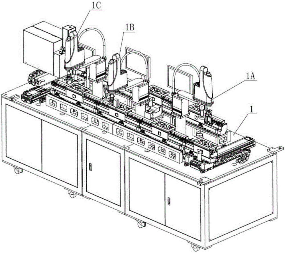
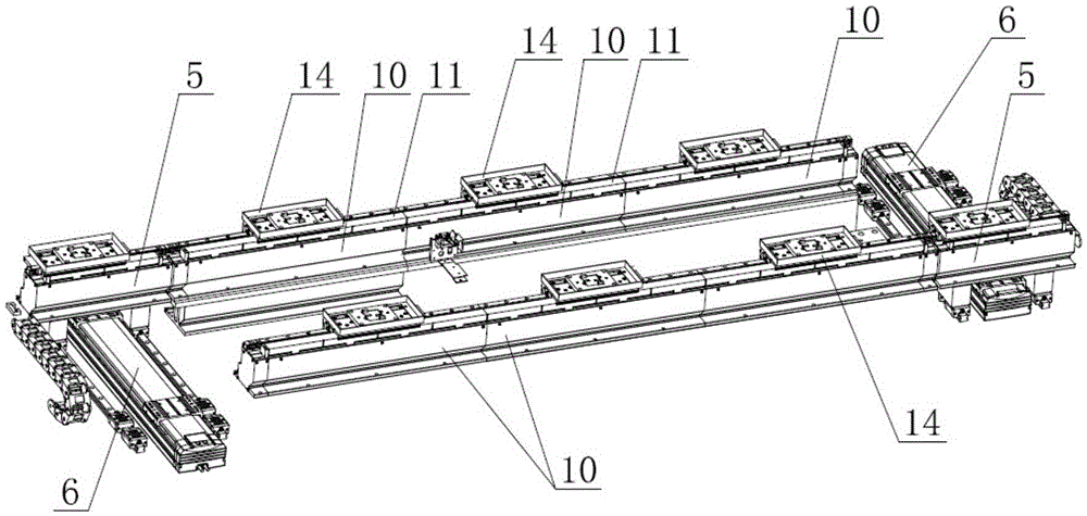
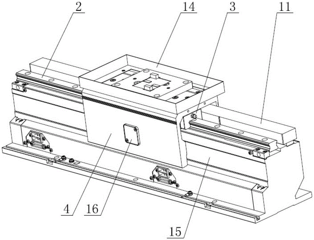
[0024] Such as Figure 1 to Figure 4 Shown is the first embodiment of a linear slider type circulation conveying production line of the present invention, including a frame 1, two fixed guide rail assemblies arranged parallel to the frame 1, slide rails 2 installed on the fixed guide rail assemblies, and The slide block 3 matched with the slide rail 2 and the moving part 4 fixedly connected with the slide block 3, the two ends of the fixed guide rail assembly are equipped with a mobile guide rail seat 5 and are used to drive the mobile guide rail seat 5 to move laterally The track-changing drive mechanism 6; the frame 1 is equipped with a loading and unloading robot 1A, a plug-in robot 1B, a...


PUM


Abstract

The invention relates to the technical field of automatic processing equipment, in particular to a linear sliding block type cyclic conveying production line. The linear sliding block type cyclic conveying production line comprises a machine frame, two fixed guide rail assemblies, sliding rails, sliding blocks and moving parts, wherein the two fixed guide rail assemblies are arranged on the machine frame in parallel; the sliding rails are mounted on the fixed guide rail assemblies; the sliding blocks are matched with the sliding rails; the moving parts are fixedly connected with the sliding blocks. The two ends of each fixed guide rail assembly are each provided with a movable guide rail seat and a rail exchanging driving mechanism used for driving the movable guide rail seat to move laterally. A feeding and discharging robot, a part plugging robot and a screwing robot are arranged on the machine frame and arranged on one side of fixed guide rail seats according to the processing sequence. By adopting the linear sliding block type cyclic conveying production line, the occupied area and investment cost of the production line can be greatly reduced, and the cost performance is higher.

Description

technical field [0001] The invention relates to the technical field of automatic processing equipment, in particular to a linear slider type circulation conveying production line. Background technique [0002] With the promotion of machine replacement projects, the traditional assembly line production line is also facing many problems of mechanized transformation, such as the difficulty of long-distance transportation and low transportation accuracy of the conveyor belt, and the use of existing connection equipment is not only expensive , the equipment takes up a lot of space, and the connection effect is difficult to meet the needs of the manufacturer, and the defects are obvious. The linear motor servo system is a power device that directly converts electrical energy into mechanical energy for linear motion. It does not have an intermediate conversion link for a rotating motor, and can effectively overcome the traditional conversion mechanism's large volume, low precision,...

Claims


Application Information

Patent Timeline
Patent Type & Authority Applications(China)
IPC IPC(8): B23P21/00
CPCB23P21/00
Inventor 李明亮张平良
Owner DONGGUAN SUMIDA AUTOMATION CO LTD
Learn More