Printing steaming tank

A steaming and printing technology, used in printing, printing machines, general parts of printing machinery, etc., can solve the problem of large difference between reactive and acid dyes, avoid the difference between shades, ensure diffusion and penetration, and ensure color fixing efficiency. Effect

Active Publication Date: 2016-06-08
MIANYANG JIAXI PRINTING & DYEING
View PDF10 Cites 1 Cited by
  • Summary
  • Abstract
  • Description
  • Claims
  • Application Information

AI Technical Summary

Problems solved by technology

[0004] The object of the present invention is to provide a kind of printing steaming tank, solve the problem that the size difference of reactive and acidic dyes in the steaming tank is large

Method used


Image

  • Printing steaming tank
  • Printing steaming tank

Examples


Embodiment 1

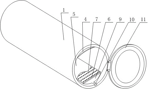
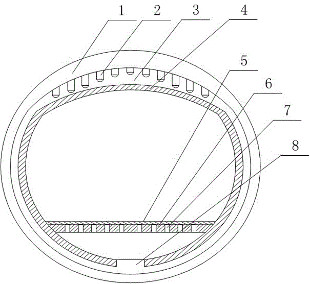
[0025] Such as figure 1 with figure 2 As shown, this embodiment includes a tank body 1 and a lid body 11 that is hinged and matched with it, and also includes a partition board 4, which is fixed on the inner wall of the tank body 1 and divides the inner circumferential wall of the tank body 1 into the upper part. The arc wall and the superior arc wall at the lower section are provided with an interlayer on the inner wall of the tank body 1, a plurality of steam nozzles 2 are fixed on the inferior arc wall, and the baffle 4 and the interlayer constitute a steam flow channel 3. A support plate 6 is installed on the superior arc wall, a plurality of steam injection holes 7 are opened on the support plate 6, and the steam flow channel 3 is provided with perforation holes 8 corresponding to the steam injection holes 7.

[0026] In the prior art, when the gray fabric is fixed, the steam is directly introduced from the side of the tank 1, and the steam at the steam inlet will be gather...

Embodiment 2

[0028] Such as figure 2 As shown, in this embodiment, the upper surface of the support plate 6 is covered with an isolation cloth 5, and a drainage channel 10 is opened at the lowest point of the superior arc wall. During the fixation process, a large amount of steam acts directly on the grey fabric through the spray holes 7 to ensure the full diffusion and penetration of the dye and fully combine the dye with the fiber. However, because the steam passes through the multiple spray holes 7 to achieve point-to-point contact with the grey fabric, The temperature at the contact point of the two is the highest, which is likely to cause local overheating. In this embodiment, a layer of insulation cloth 5 is covered on the upper surface of the support plate 6, and the conductivity of the steam on the insulation cloth 5 is used to make the steam pass through the insulation The cloth 5 is in full contact with the bottom of the grey cloth, so as to prevent the grey cloth in the tank bod...

Embodiment 3

[0032] Such as figure 2 As shown, in this embodiment, the partition 4 is arranged in an arc shape. Compared with a flat partition 4, the smooth surface of the partition 4 can be used to divert the steam ejected from the steam nozzle 2 to avoid The steam bounces and impacts on the partition 4 to ensure the flow rate of the steam to improve the color fixing efficiency of the grey fabric.


PUM


Abstract

The invention discloses a printing steaming tank. The printing steaming tank comprises a tank body, a cover body and a separating plate, wherein the separating plate is fixed to the inner wall of the tank body and divides the inner circumferential wall of the tank body into a minor arc wall located on the upper section and a major arc wall located on the lower section; an interlayer is arranged on the inner wall of the tank body; a plurality of steam spraying nozzles are fixed to the minor arc wall; a steam runner is formed by the separating plate and the interlayer; a supporting plate is installed on the major arc wall and provided with a plurality of steam spraying holes; and the steam runner is provided with jetting holes corresponding to the steam spraying holes. Before interacting with gray fabric, steam moves by a certain distance in the steam runner until moving into a steam collecting cavity, and the temperature of the steam is gradually decreased in the moving process of the steam, so that the steam concentrated in the steam collecting cavity does not become overheated steam. Thorough diffusion and permeation of dye are guaranteed, the dye is thoroughly combined with fibers, coloring of active and acid dye is facilitated, and color differences between lab samples and bulk samples and large shade differences of the gray fabric are avoided.

Description

Technical field [0001] The invention relates to a steaming tank, in particular to a printing steaming tank. Background technique [0002] The reactive dye printing process includes white cloth printing-drying-steaming (102~104℃, 5~7min) or baking-cold running water washing-hot water washing-soaping-hot water washing-cold water washing-drying. In the steaming process, that is, the fixing process, the reaction speed of the reactive dye and the fiber increases with the increase of temperature. The high temperature treatment under a certain humidity is conducive to the full diffusion and penetration of the dye, and the dye and fiber are fully combined, and the steaming time Depending on the reactivity of the dye, for dyes with slow reaction speed, the steaming time can be extended to 8~10min. [0003] In the prior art, a steaming tank is usually used for color fixation. However, the steaming tank is designed to take in steam directly from the bottom of the side without any cooling mea...

Claims


Application Information

Patent Timeline
Patent Type & Authority Applications(China)
IPC IPC(8): B41F23/04
CPCB41F23/0433
Inventor 周海龙
Owner MIANYANG JIAXI PRINTING & DYEING
Why Eureka
Try Eureka