
Excitation circuit for electromagnetic flow meter

A technology of electromagnetic flowmeter and excitation circuit, which is applied in the direction of measuring flow/mass flow, liquid/fluid solid measurement, measuring device, etc., which can solve the problem of increased circuit board size, increased overall power consumption of electromagnetic flowmeter, and large storage power loss, etc. problem, to achieve the effect of eliminating power loss

Inactive Publication Date: 2016-06-08
DEYANG NEWPEACE AUTOMATION INSTR CO LTD
View PDF8 Cites 2 Cited by
  • Summary
  • Abstract
  • Description
  • Claims
  • Application Information

AI Technical Summary

Problems solved by technology

The constant current circuit of the above patent uses operational amplifiers and transistors to form an analog linear constant current circuit. It also loses a lot of storage power and requires the use of a radiator. The heat generated by the radiator will increase the temperature of the circuit board and affect the performance of the circuit board. Due to the use of radiators, the size of the circuit board will increase, and the overall cost of the circuit design will be high. The most important thing is that the overall power consumption of the electromagnetic flowmeter will increase a lot due to the large loss of useless power.

Method used


Image

  • Excitation circuit for electromagnetic flow meter
  • Excitation circuit for electromagnetic flow meter

Examples


Embodiment 1

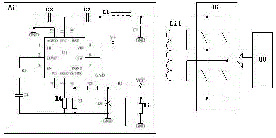
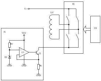
[0027] like figure 1 As shown, the excitation circuit is used for electromagnetic flowmeter. The excitation circuit is composed of constant current circuit Ai, sensing coil Li1, H bridge circuit Hi, and H bridge circuit control circuit U0. The constant current circuit Ai is the sensor through the H bridge circuit Hi. The coil Li1 provides a constant current, each control signal output terminal of the H-bridge circuit control loop U0 is respectively connected to each control terminal of the H-bridge circuit Hi, and the two ends of the sensing coil Li1 are respectively connected to the two output terminals of the H-bridge circuit Hi , to provide a constant current to the H-bridge circuit Hi.

[0028] The constant current circuit Ai is a switch mode constant current circuit, which consists of a switch drive chip U1 (or a synchronous step-down DC-DC regulator chip), a start-up circuit, a switching frequency selection circuit, an error amplification compensation circuit and an out...


PUM


Abstract

The invention discloses an excitation circuit for an electromagnetic flow meter. The excitation circuit comprises a constant current circuit, a sensing coil, an H-bridge circuit and an H-bridge circuit control loop; the constant current circuit provides a constant current for the sensing coil through the H-bridge circuit, all control signal output ends of the H-bridge circuit control loop are connected to all control ends of the H-bridge circuit respectively, and the two ends of the sensing coil are connected to the two output ends of the H-bridge circuit respectively; the constant current circuit is a switching-mode constant current circuit and comprises a switch driving chip, a starting circuit, a switch frequency selection circuit, an error amplification and compensation circuit and an output filtering circuit; the output end of the switch driving chip is connected to a positive input of the H-bridge circuit through the output filtering circuit, a negative input of the H-bridge circuit is grounded through a current sampling resistor, and the switch driving chip collects a current signal through the current sampling resistor, so that voltage input to the H-bridge circuit is variable direct voltage, and the current passing through the sensing coil is constant.

Description

technical field [0001] The invention relates to electromagnetic flowmeter technology, in particular to a switch-mode constant current excitation circuit for sensor coils of the electromagnetic flowmeter. Background technique [0002] An electromagnetic flowmeter is an instrument used to measure fluid flow. The excitation circuit is an indispensable and important part of the electromagnetic flowmeter. Its function is to generate an excitation current with a controlled size and timing to excite the sensor coil to generate a magnetic field. The fluid cuts the magnetic field lines in the pipeline, and induces electromotive force at both ends of the signal electrode. The magnitude of the induced electromotive force is proportional to the magnetic induction intensity and the flow velocity of the fluid. [0003] Existing electromagnetic flowmeters keep the magnetic field strength constant by controlling the excitation current. The existing typical excitation circuits used in elect...

Claims


Application Information

Patent Timeline
Patent Type & Authority Applications(China)
IPC IPC(8): G01F1/60
CPCG01F1/60
Inventor 查华明方毅张艺耀
Owner DEYANG NEWPEACE AUTOMATION INSTR CO LTD
Features
  • Generate Ideas
  • Intellectual Property
  • Life Sciences
  • Materials
  • Tech Scout
  • Unparalleled Data Quality
  • Higher Quality Content
  • 60% Fewer Hallucinations
Learn More