Laser projection device

A technology of laser projection and equipment, applied in the field of projection, can solve the problems of low cooling efficiency, deformation of light-transmitting mirror, damage to laser light source components, etc., and achieve the effects of improving heat dissipation efficiency, simplifying structure, and improving dust resistance.

Active Publication Date: 2016-06-08
QINGDAO HISENSE LASER DISPLAY CO LTD
View PDF5 Cites 10 Cited by
  • Summary
  • Abstract
  • Description
  • Claims
  • Application Information

AI Technical Summary

Problems solved by technology

If the temperature is too high, it will affect the working efficiency and fluorescence conversion efficiency of the laser light source parts, and even damage the laser light source parts. Work
[0004] In the prior art, a fan is used to blow the heat source components inside the laser projection device. At this time, on the one hand, the cooling efficiency is low, and on the other hand, the fan will blow the external dust into a dust-sensitive part of the heat source components.

Method used


Image

  • Laser projection device
  • Laser projection device
  • Laser projection device

Examples


Embodiment 1

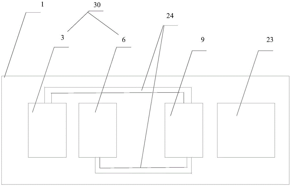
[0037] In the embodiment of the present invention, the components of the laser projection device include at least two parts: a first part: a heat source component; a second part: a power board and / or a driving board. Wherein, the heat source component includes at least a laser light source component and an optomechanical component.

[0038] Optionally, the laser light source component is a closed structure that is closed with a first casing. Optionally, the optomechanical component is a closed structure that is sealed by a second casing.

[0039] Optionally, the laser light source component includes at least a laser and a fluorescent wheel. Optionally, the laser light source component further includes a first optical lens. Optionally, the optomechanical component includes at least a digital micromirror device (DigitalMicromirrorDevice, DMD for short). Optionally, the optomechanical component further includes a second optical lens.

[0040] In laser projection equipment, th...

Embodiment 2

[0090] Based on the same idea, an embodiment of the present invention also provides a laser projection device.

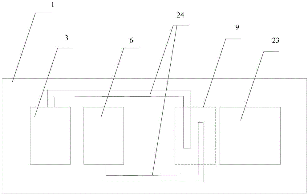
[0091] Figure 3a A schematic diagram of a laser projection device applicable to an embodiment of the present invention is exemplarily shown, such as Figure 3a As shown, the laser projection device provided by the embodiment of the present invention includes:

[0092] A heat source component; the heat source component includes at least a laser light source component and an optomechanical component; wherein, the laser light source component includes a sealed casing outside; the laser light source component is a closed structure that is sealed by the first casing;

[0093] A heat pipe, one end of the heat pipe is connected to the heat source part, and the other end is connected to the heat concentration module; it is used to export the heat generated by each part of the heat source part to the heat concentration module;

[0094] The heat concentration module is loc...

Embodiment 3

[0110] Based on the same idea, an embodiment of the present invention provides a laser projection device. The laser projection device provided in the third embodiment is applicable to the laser projection device provided in the first embodiment above, and is also applicable to the laser projection device provided in the second embodiment above. That is to say, optionally, the laser light source component in the laser projection device provided in the third embodiment may or may not include a sealed casing.

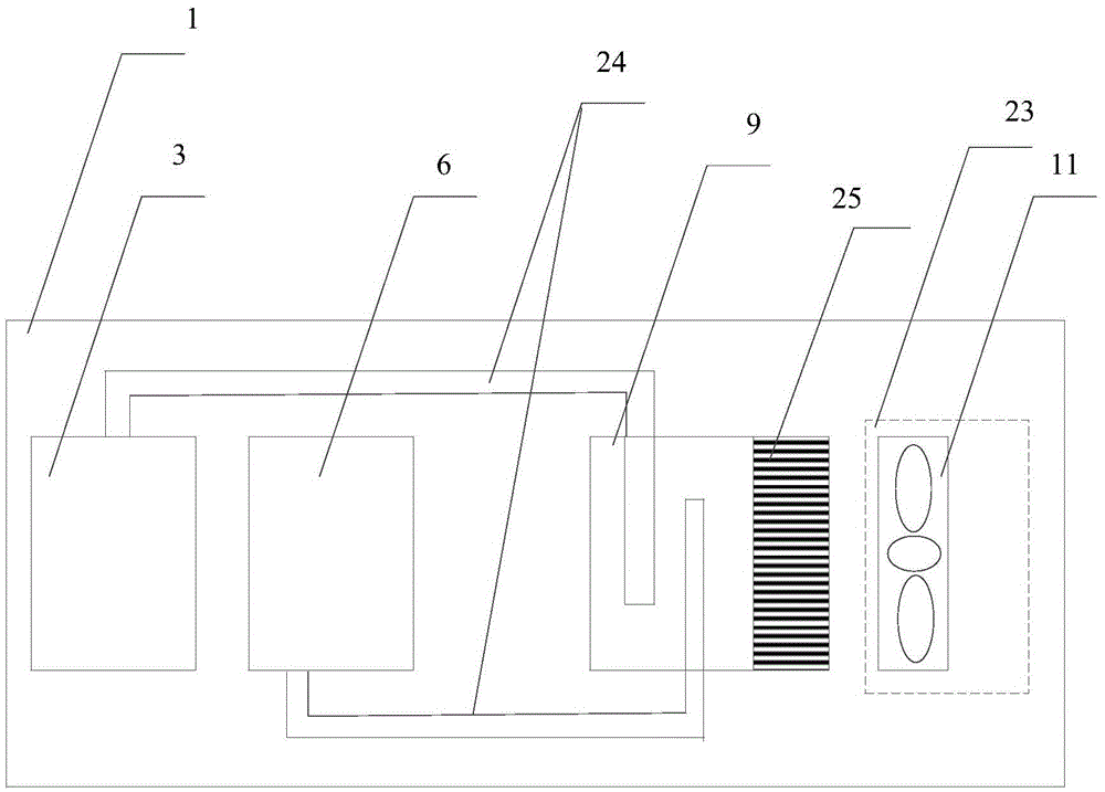
[0111] Figure 4a A schematic structural diagram of a laser projection device provided by an embodiment of the present invention is shown as an example. Such as Figure 4a As shown, laser projection equipment includes:

[0112] Heat source components; heat source components include at least laser light source components and optomechanical components;

[0113] A heat pipe, one end of the heat pipe is connected to the heat source part, and the other end is connected to t...


PUM


Abstract

The embodiment of the invention relates to the technical field of projection, in particular to a laser projection device. On the one hand, the laser projection device is used for improving the dust prevention degree of dust sensitive parts inside the laser projection device; and on the other hand, the laser projection device aims at improving the heat dissipation efficiency of a heat source part inside the laser projection device. In the embodiment, a laser source part externally comprises a sealing shell, and the dust prevention degree of the laser source part is improved. Further, heat produced by the laser source part and heat produced by a laser machine part are both guided into a heat centralizing module through heat guide tubes, the heat on the heat centralizing module is dissipated through heat dissipation modules in a centralized mode, the purpose of dissipating the heat of the laser source part and the laser machine part is achieved, direct heat dissipation conducted on the laser source part and the laser machine part is not needed in the process, and the problem that dust is brought to the laser source part and the laser machine part in the heat dissipation process is prevented. In addition, due to the fact that the heat on the heat centralizing module is dissipated in the centralized mode, the heat dissipation efficiency is improved.

Description

technical field [0001] Embodiments of the present invention relate to the field of projection technology, and in particular, to a laser projection device. Background technique [0002] At present, projectors have been widely used in various fields. A projector is a device that receives a video signal from a computer and then projects the video signal onto a projection screen or a wall. With the development of projectors, because lasers have many advantages such as high brightness and wide color gamut, laser projection equipment using lasers as light sources has been widely used. Laser projection equipment generally includes laser light source components and optomechanical components. The laser light source components generally include lasers and some light-transmitting mirrors. Lasers and light-transmitting mirrors in the optical path are very precise components and are very sensitive to dust. Dust enters the laser display system and adheres to the light-transmitting mirror...

Claims


Application Information

Patent Timeline
Patent Type & Authority Applications(China)
IPC IPC(8): G03B21/16G03B21/14
CPCG03B21/145G03B21/16
Inventor 张琰
Owner QINGDAO HISENSE LASER DISPLAY CO LTD
Why Eureka
Try Eureka