
A kind of manufacturing method of ultraviolet led curing optical system

A technology of optical system and production method, which is applied in the directions of instruments, calculations, and electrical digital data processing, etc., can solve the problems of low energy utilization rate, high light intensity in the intermediate curing area, and decreased uniformity, so as to meet the requirements of ultraviolet curing and energy utilization rate. High, time-saving effect

Active Publication Date: 2019-04-09
SOUTH CHINA UNIV OF TECH
View PDF5 Cites 0 Cited by
  • Summary
  • Abstract
  • Description
  • Claims
  • Application Information

AI Technical Summary

Problems solved by technology

[0004] Most of the ultraviolet LED devices currently on the market are arranged in a rectangular array of LEDs, and each lamp bead is directly irradiated on the surface of the cured object, which leads to a problem: the light spot formed by the lamp bead overlaps with the light spot formed by the surrounding lamp bead, and the High light intensity in the middle curing area, low light intensity in the edge area
Low energy utilization rate and poor uniformity. After the working distance slightly deviates from the fixed working distance, the uniformity will drop seriously

Method used


Image

  • A kind of manufacturing method of ultraviolet led curing optical system
  • A kind of manufacturing method of ultraviolet led curing optical system
  • A kind of manufacturing method of ultraviolet led curing optical system

Examples


Embodiment 1

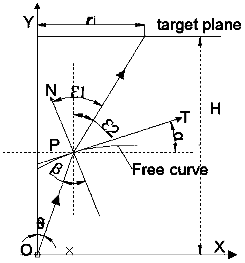
[0057] Such as figure 1 Shown, a kind of fabrication method of ultraviolet LED curing optical system comprises the following steps:

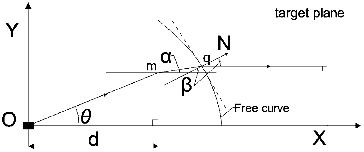
[0058] Step 1: Establish a plane coordinate system with the coordinate origin O(0,0), including the X-axis and Y-axis, take the coordinate origin O as the ultraviolet LED light source, and deduce the coordinate iteration relationship of the following two free curve discrete points;

[0059] a) The making of the outline of the free-form surface of the outer lens;

[0060] Such as figure 1 As shown, the angle between the light emitted by the light source O and the Y axis is θ, and the angle between the normal line at the intersection of the outgoing light and the free curve of the outer lens and the outgoing light is ε1, when θ is θ i , the light emitted from point O of the light source passes through the i-th point p on the free curve of the outer lens i (x i ,y i ) reaches the receiving screen after refraction, θ i and θ i+1 respectively ...

Embodiment 2

[0094] A method for manufacturing an ultraviolet LED curing optical system, comprising the following steps:

[0095] Step a: Use the LED curing line light source lens model described in Step 3 of Example 1, with the same material and size as Example 1;

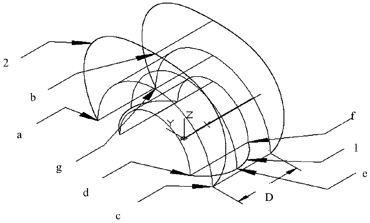
[0096] Step b: Arrange the LED curing line light source lens models in the six steps a in an arc-shaped integrated arrangement with an included angle θ of 2.5° to obtain an ultraviolet LED curing surface light source optical system that produces a large rectangular spot. The physical model is as follows Figure 4 shown, and then imported into the TracePro optical simulation software to verify and analyze the built model. The working distance is 50mm, Figure 6a and 6b Respectively, the illumination distribution spot diagram and curve diagram on the receiving plane. Depend on Figure 6a It can be obtained that the light is basically controlled in a long rectangular spot with a length of about 120 and a width of about 100mm....


PUM


Abstract

The invention relates to a making method of an ultraviolet LED curing optical system. The ultraviolet LED curing optical system comprises an outer lens and an inner lens. The making method comprises the following steps that 1, a plane-coordinate system is established by taking O as a coordinate origin, and a free curve of the outer lens and a free curve of the inner lens are made by taking the coordinate origin of the plane-coordinate system as a light source O of an ultraviolet LED; 2, an iteration relation is well programmed, an initial value is given, and discrete points of the free curve of the inner lens and the free curve of the outer lens are calculated through MATLAB; 3, coordinates of the discrete points are introduced into CAD modeling software successively, the outer lens and the inner lens are constructed, the inner lens collimates light rays in the rotation direction, the outer lens controls distribution of the collimated light rays, ultraviolet LED curing line light source optical lens models are obtained through combination, the line light source optical lens models are integrally arranged, and the ultraviolet LED curing surface light source optical system is obtained. The making method of the ultraviolet LED curing optical system has the advantages of being capable of obtaining lenses with different shapes and the like.

Description

technical field [0001] The invention relates to the technical field of ultraviolet LED curing, in particular to a method for manufacturing an ultraviolet LED curing optical system. Background technique [0002] Ultraviolet LED is a new technology emerging with LED. It is mainly used in curing fields, such as printing, ink curing, UV glue and other industries. Compared with traditional curing sources such as high-pressure mercury lamps and metal halide lamps, ultraviolet LEDs are energy-saving, environmentally friendly Long life, open or close at any time and so on. With the maturity of UV LED technology, it will soon replace the traditional curing light source. [0003] Since the light emitted by the ultraviolet LED light source is approximately Lambertian, that is, the light intensity is cosine-distributed, it cannot be directly used for curing, and secondary light distribution is required. [0004] Most of the UV LED devices currently on the market are arranged in a rect...

Claims


Application Information

Patent Timeline
Patent Type & Authority Patents(China)
IPC IPC(8): G06F17/50
CPCG06F30/367
Inventor 文尚胜向昌明陈志涛张志清
Owner SOUTH CHINA UNIV OF TECH
Learn More