Power good signal output method and device
A signal output and signal technology, which is applied in the field of good power signal output methods and devices, can solve problems such as affecting the accuracy of power good state judgment, affecting the overall performance of display driver chips, and protecting circuit misoperations, so as to solve competition and risk-taking problems. , the effect of eliminating burr phenomenon, zero power consumption static current
- Summary
- Abstract
- Description
- Claims
- Application Information
AI Technical Summary
Problems solved by technology
Method used
Image
Examples
Embodiment 1
[0078] FIG. 7(A) shows the circuit diagram of the power good signal output subunit of Embodiment 1 of the present invention, and FIG. 7(B) shows the effect diagram of the power good signal output subunit of Embodiment 1 of the present invention.
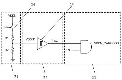
[0079] As shown in Figure 7(A), the power good signal output subunit of the present invention includes a voltage divider module 221 with an enable switch 224, a forward judgment module 222 and a trigger 223, wherein the enable switch 224 is close to the ground wire terminal (GND terminal).
[0080] Wherein, the voltage dividing module 221 converts the input power supply voltage VDDN into a detection divided voltage VDDN' that can be judged by dividing the voltage by resistors. Since the voltage divider module 221 is provided with an enable switch 224 responsive to the enable signal EN, the static power consumption of the voltage divider resistor string can be zero in deep sleep or shutdown mode through the control of the enable signa...
Embodiment 2
[0089] FIG. 8(A) shows the circuit diagram of the power good signal output subunit of the second embodiment of the present invention, and FIG. 8(B) shows the effect diagram of the power good signal output subunit of the second embodiment of the present invention.
[0090] As shown in FIG. 8(A), the power good signal output subunit of the present invention includes a voltage divider module 321 with an enable switch 324, a forward judgment module 322 and a trigger 323, wherein the enable switch 324 is close to the power supply voltage end (VDDN end).
[0091] Wherein, the voltage dividing module 321 converts the input power supply voltage VDDN into a detection divided voltage VDDN' that can be judged by dividing the voltage by resistors. Since the voltage divider module 321 is provided with an enable switch 324 that responds to the enable signal EN, the static power consumption of the voltage divider resistor string can be zero in deep sleep or shutdown mode through the control ...
Embodiment 3
[0100] FIG. 9(A) shows the circuit diagram of the power good signal output subunit of the third embodiment of the present invention, and FIG. 9(B) shows the effect diagram of the power good signal output subunit of the third embodiment of the present invention.
[0101] As shown in Figure 9(A), the power good signal output subunit of the present invention includes a voltage divider module 421 with an enable switch 424, a reverse judgment module 422 and a trigger 423, wherein the enable switch 424 is close to the power supply voltage end (VDDN end).
[0102] Wherein, the voltage dividing module 421 converts the input power supply voltage VDDN into a detection divided voltage VDDN' that can be judged by dividing the voltage by resistors. Since the enable switch 424 is provided in the voltage divider module 421 in response to the enable signal EN, the static power consumption of the voltage divider resistor string can be zero in deep sleep or shutdown mode through the control of ...
PUM
 Abstract
Description
Claims
Application Information
 - R&D
- Intellectual Property
- Life Sciences
- Materials
- Tech Scout
- Unparalleled Data Quality
- Higher Quality Content
- 60% Fewer Hallucinations
Browse by: Latest US Patents, China's latest patents, Technical Efficacy Thesaurus, Application Domain, Technology Topic, Popular Technical Reports.
© 2025 PatSnap. All rights reserved.Legal|Privacy policy|Modern Slavery Act Transparency Statement|Sitemap|About US| Contact US: help@patsnap.com


