A cooling device for a power battery

A heat dissipation device and power battery technology, applied to secondary batteries, circuits, electrical components, etc., can solve the problems of overweight heat dissipation fins, bulky volume, complex process, etc., achieve good heat dissipation effect, less material consumption, The effect of enhancing the heat transfer effect

Active Publication Date: 2018-12-07
SHANGHAI UNIV OF ENG SCI
View PDF3 Cites 0 Cited by
  • Summary
  • Abstract
  • Description
  • Claims
  • Application Information

AI Technical Summary

Problems solved by technology

The heat dissipation fins of this patent are prepared by extrusion process, which is relatively complex and time-consuming, and the heat dissipation fins produced are too heavy and bulky, so they cannot be used in power plants that require high weight and volume, such as automobiles. battery system

Method used


Image

  • A cooling device for a power battery
  • A cooling device for a power battery
  • A cooling device for a power battery

Examples


Embodiment Construction

[0045] The present invention will be further described below in conjunction with accompanying drawing.

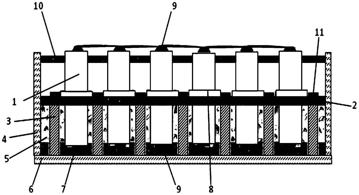
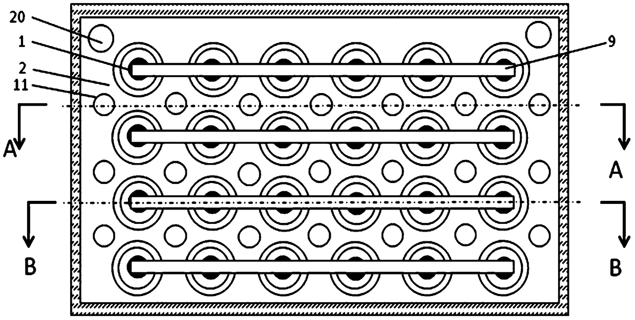
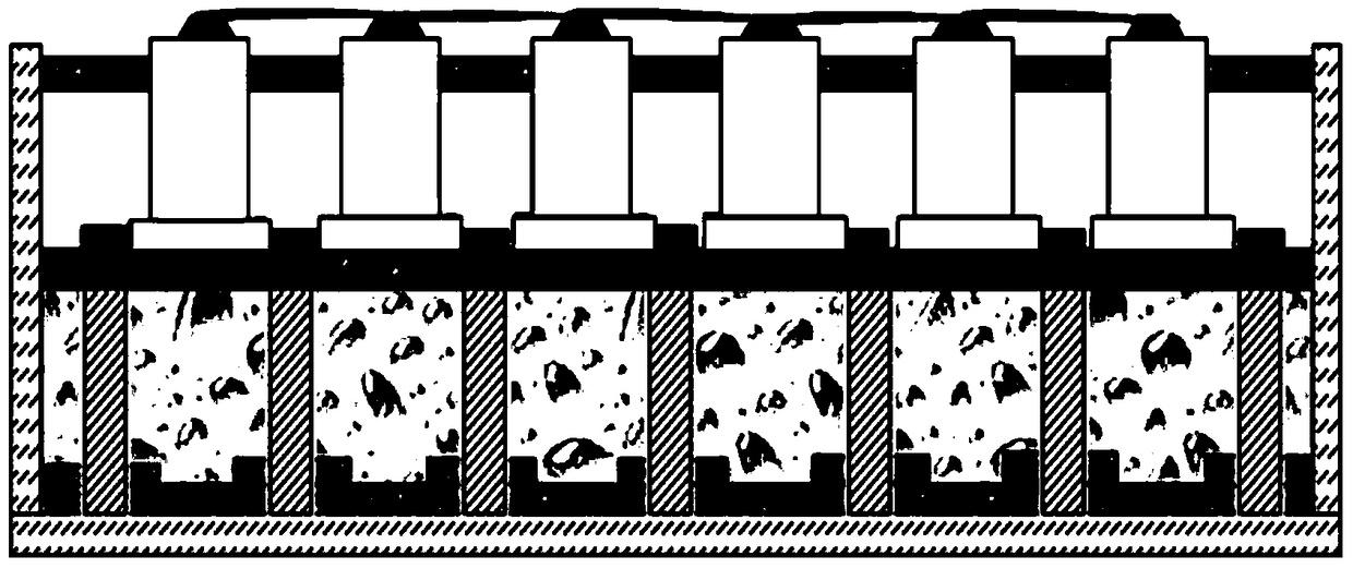
[0046] like Figure 1~5 As shown, several cylindrical batteries 1 are vertically arranged at intervals in the battery pack box with the opening upward, and the batteries 1 may be in the shape of a square column, a cylinder, or an aluminum-plastic film soft bag, etc. Near the top of the battery 1, an upper insulating plate 10 is arranged in the battery pack box, the upper insulating positioning plate 10 is tightly sleeved on the battery 1, and the lower insulating plate 7 is cushioned between the bottom of the battery 1 and the bottom plate 6 of the battery pack box.

[0047] A thermal diffusion plate 2 is arranged between the upper insulating positioning plate 10 and the buffer lower insulating plate 7. The thermal diffusion plate 2 is a metal plate with high thermal conductivity such as aluminum, copper, titanium, iron, etc., and the thickness is 0.3-3mm. 2 The outer surf...


PUM

PropertyMeasurementUnit
phase transition temperatureaaaaaaaaaa
thicknessaaaaaaaaaa
melting pointaaaaaaaaaa

Abstract

The invention discloses a heat dissipation device of a power battery. A plurality of cylindrical battery bodies are vertically arranged in a battery pack box with an upward opening at intervals; an upper insulating positioning plate is arranged at the portion, close to the tops of the battery bodies, inside the battery pack box, and the battery bodies are closely sleeved with the upper insulating positioning plate; a lower buffering insulating plate is padded between the bottoms of the battery bodies and the bottom of the battery pack box; a heat diffusion plate is arranged between the upper insulating positioning plate and the lower buffering insulating plate, and the outer edge of the heat diffusion plate is closely attached to the side wall of the battery pack box; through holes corresponding to the battery bodies are formed in the heat diffusion plate and provided with enlarged heat diffusion bodies, the outer walls of the battery bodies are closely sleeved with the enlarged heat diffusion bodies, and the portions between the enlarged heat diffusion bodies and the battery bodies are filled with interface heat conduction material layers; a plurality of heat conduction columns are arranged on the peripheries of the battery bodies at intervals, and upper ends and the lower ends of the heat conduction columns are in close contact with the heat diffusion plate and the battery pack box respectively; the lower portion of the heat diffusion plate is filled with a phase-change material layer or a thermoplastic encapsulating material layer. The heat dissipation device is excellent in heat transfer augmentation effect, better in heat dissipation effect, more even in temperature distribution, compact in appearance, simple in structure and suitable for a power battery system.

Description

technical field [0001] The invention relates to the technical field of power battery cooling, in particular to a composite heat dissipation device with a thermal diffusion plate and a thermal conduction column. Background technique [0002] Power batteries such as lithium-ion batteries have high energy density, small size, and long cycle life. They have great application potential and market in electric passenger cars and commercial vehicles. However, since the temperature rise of the lithium-ion battery during charging and discharging affects its performance and cycle life, too high temperature may even cause thermal runaway, resulting in accidents such as spontaneous combustion and explosion. The temperature of the conventional lithium cobaltate cathode material battery needs to be controlled at 50 degrees Celsius. Within, to avoid thermal runaway and fire explosion, improve safety. With the advancement of battery materials and processes, although the operating temperatur...

Claims


Application Information

Patent Timeline
Patent Type & Authority Patents(China)
IPC IPC(8): H01M10/613H01M10/625H01M10/655H01M10/6554H01M10/659
CPCY02E60/10
Inventor 张恒运夏欣王之伟金光灿
Owner SHANGHAI UNIV OF ENG SCI
Why Eureka
Try Eureka