
Pulse transfusion micropump

A pulse and micropump technology, applied in the field of infusion pumps, can solve the problems of low pressure, high price, inconvenience, etc., and achieve the effects of continuous washing and drainage, convenient drug administration, and large spraying force of the drug solution

Active Publication Date: 2016-06-15
SECOND MILITARY MEDICAL UNIV OF THE PEOPLES LIBERATION ARMY
View PDF5 Cites 10 Cited by
  • Summary
  • Abstract
  • Description
  • Claims
  • Application Information

AI Technical Summary

Problems solved by technology

[0003] However, in actual work, this work mainly relies on the manual injection of the syringes of medical staff, which is very inconvenient, especially the syringe needs to be removed every time it is pushed, which not only increases the risk of hygienic infection, but also increases the burden on medical staff. In clinical practice, regular and quantitative boluses are required. This requirement is not easy to achieve for humans. After all, it is impossible for medical staff to be by the patient's side all the time.
[0004] Existing injection pumps on the other hand, such as the WZS-50F6 type double-channel micro-injection pump (Zhejiang Zhejiang University) Japan Terumo Terumo TE-331 injection pump (Japan Terumo Terumo) all imitate the use of syringe injections by hand, It is impossible to complete the pulse drug administration, and more importantly, its pressure is low, and it is impossible to complete the above-mentioned treatment process of driving "the impact of the drug liquid to break the thrombus blocking the vascular access". At the same time, the structure is complicated and the price is too high. suitable for heavy use

Method used


Image

  • Pulse transfusion micropump

Examples


Embodiment 1

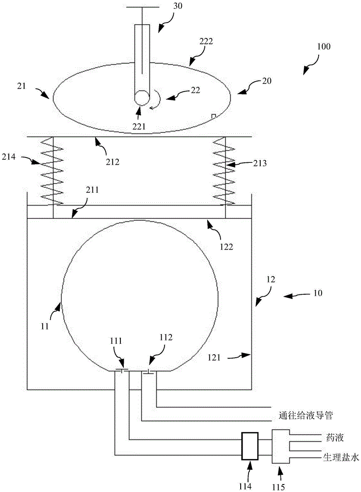
[0020] figure 1 It is a schematic structural diagram of the pulse infusion micropump according to the embodiment of the present invention

[0021] The pulse infusion micropump 100 includes a liquid medicine cavity unit 10 , a pulse extrusion unit 20 connected thereto for extruding the liquid medicine therein, a controller (not shown in the figure) and a screw adjustment mechanism 30 .

[0022] Wherein, the liquid medicine cavity unit 10 is used to accommodate the liquid medicine, including a hollow spherical liquid medicine chamber 11 and a protective cover 12,

[0023] The liquid medicine chamber 11 is spherical, and is provided with a liquid inlet 111 and a liquid outlet 112. The liquid inlet 111 and the liquid outlet 112 are horizontally arranged at the lower part of the liquid medicine chamber 11, and a limited liquid medicine sheet is arranged on the liquid inlet 111. To the one-way valve entering, the liquid outlet 112 is provided with a one-way valve that limits the on...


PUM


Abstract

The invention provides a pulse transfusion micropump which is used for delivering medical solution or normal saline pulse to a solution catheter which is disposed in a vessel. The pulse transfusion micropump is characterized by including the following: a medicine solution cavity unit for accommodating medicine solution, the medicine solution cavity provided with a solution inlet and a solution outlet thereon, the solution inlet provided with a one-way valve thereon for defining one way entrance of the medicine solution, the solution outlet provided with a one-way valve thereon for defining one way exit of the medicine solution; a pulse excruciating unit which is communicated with the medicine solution cavity and is used for excruciating the medicine cavity and includes a reciprocating piece and a power source, the reciprocating piece being communicated with the medicine solution, the power source providing power to the reciprocating piece. The pulse transfusion micropump has a large injection force in terms of the medicine solution, can perform solution washing and solution discharging, which greatly facilitates medicine feeding of medical staff. The medicine solution cavity of the pulse transfusion micropump has no moving pieces, no wearing, and does not introduce material pollution.

Description

technical field [0001] The invention belongs to the field of medical devices, in particular to an infusion pump for pumping thrombolytic liquid or physiological saline. Background technique [0002] In the clinical treatment of vascular diseases, minimally invasive treatment methods are often used. The thrombolytic drug solution is pushed to the thrombus site in the blood vessel through a syringe and a special catheter, that is, the pressure of the thrombolytic drug is sprayed onto the thrombus, and the high-speed and high-pressure (compared to In terms of thrombus in the blood), the impact of the drug liquid breaks the thrombus blocking the vascular access, while the smaller thrombus is ablated under the action of the thrombolytic drug to achieve the purpose of eliminating the thrombus in the blood vessel. [0003] However, in actual work, this work mainly relies on the manual injection of the syringes of medical staff, which is very inconvenient, especially the syringe nee...

Claims


Application Information

Patent Timeline
Patent Type & Authority Applications(China)
IPC IPC(8): A61B17/22
CPCA61B17/22004A61B2017/00539A61B2017/00778A61B2017/22084
Inventor 魏小龙吴雅妮景在平赵志青周建
Owner SECOND MILITARY MEDICAL UNIV OF THE PEOPLES LIBERATION ARMY
Learn More