Fire detection pipe automatic fire extinguishing device used in alternating-current and direct-current power system in transformer substation

A DC power supply system and automatic fire extinguishing technology, applied in fire rescue and other fields, can solve the problems of heavy cleaning workload, personal injury, unsuitable high-voltage electrical equipment, etc., and achieve the effect of fast detection response time and reduced losses

Inactive Publication Date: 2016-06-15
SHANGHAI MUNICIPAL ELECTRIC POWER CO
View PDF5 Cites 9 Cited by
  • Summary
  • Abstract
  • Description
  • Claims
  • Application Information

AI Technical Summary

Problems solved by technology

[0011] However, the fire detection tube in this technical solution is coiled on the object to be protected, which is not suitable for high-voltage electrical equipment (because there is a problem of high voltage insulation from the ground). In addition, the technical solution is located in the space where the object to be protected The fully submerged spraying is used in the system, and dry powder is used as the fire extinguishing agent, which has the disadvantage of a large amount of cleaning work after the event. For some precision power equipment and switchgear/control cabinets with complex structures in the substation, this cleaning work is performed at the equipment operation site (substation , power distribution station) is actually impos

Method used


Image

  • Fire detection pipe automatic fire extinguishing device used in alternating-current and direct-current power system in transformer substation
  • Fire detection pipe automatic fire extinguishing device used in alternating-current and direct-current power system in transformer substation

Examples


Example Embodiment

[0043] The present invention will be further described below in conjunction with the drawings.

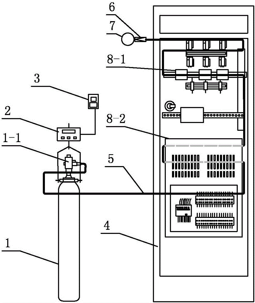
[0044] figure 1 Among them, the technical scheme of the present invention provides an automatic fire extinguishing device for fire detection pipes for AC and DC power supply systems in substations, including a fire extinguishing agent bottle 1 and a fire detection pipe 5 connected to the outlet of the fire extinguishing agent bottle; The fire extinguishing agent outlet of the fire extinguishing agent bottle is provided with a fire extinguishing agent release valve 1-1; the head end of the fire detection pipe is connected to the fire extinguishing agent outlet of the fire extinguishing agent bottle through the fire extinguishing agent release valve; The end of the fire detection tube is in a blocked state; its characteristics are:

[0045] The fire extinguishing agent is carbon dioxide gas;

[0046] The fire extinguishing agent bottle is arranged near the AC or DC power supply cabinet or ...


PUM

PropertyMeasurementUnit
Lengthaaaaaaaaaa

Abstract

The utility model relates to an automatic fire extinguishing device for a fire detection tube used in an AC and DC power supply system in a substation, belonging to the field of fire protection. The gas fire extinguishing agent bottle is set near the AC and DC power supply cabinet or control cabinet in the substation; the fire extinguishing agent bottle is equipped with a weighing device to weigh the weight of the fire extinguishing agent in the bottle in real time; When a fire breaks out in the protected object, the fire detection tube above the protected object will melt and explode at the point where it first reaches the melting point, and the gas fire extinguishing agent in the fire detection pipe will be released, and the fire extinguishing agent release valve will be activated, and the fire extinguishing agent bottle will flow from the fire extinguishing agent bottle immediately. The gas fire extinguishing agent is continuously released in the fire detection tube, and the non-submerged fire extinguishing agent release mode is adopted. The gas fire extinguishing agent is sprayed from the melting blast hole of the fire detection tube to the root of the fire source, and the fire source is effectively extinguished instantly, and the protected object The flame just generated due to over-current or over-temperature is extinguished in the bud, and at the same time, the passive alarm contact in the weighing device is closed, and an alarm signal is output to the outside.

Description

technical field [0001] The invention belongs to the field of fire protection, in particular to an automatic fire extinguishing device used for AC and DC power supply systems in substations. Background technique [0002] The design of my country's substation fire alarm system requires that smoke detectors or smoke detectors be installed in each fire prevention area according to the "Code for Fire Protection of Thermal Power Plants and Substations" (GB50229-2006) and "Code for Design of Automatic Fire Alarm Systems" (GB50116-2013). Gas-type smoke detectors; the design of substation fire-fighting systems requires that fire-fighting equipment such as mobile fire extinguishers and yellow sand boxes be arranged in appropriate places according to the "Code for Design of Building Fire Extinguishers Configuration" (GB50140-2005). [0003] In the substation, currently only the "main transformer" with a capacity of 125MVA and above (in a substation, the transformer with the same voltage...

Claims


Application Information

Patent Timeline
IPC IPC(8): A62C3/16A62C37/10
CPCA62C3/16A62C37/10
Inventor 袁成杨心平戴春怡张思良姜圣菲钱国华
Owner SHANGHAI MUNICIPAL ELECTRIC POWER CO
Why Eureka
Try Eureka