
Efficient treatment device for industrial waste gas

A treatment device, industrial waste gas technology, applied in the direction of separation device, combination device, separation method, etc., can solve the problems of low dust filtration effect, lack of self-protection of workers, low cleaning ability of dust collection device, etc., to achieve improved effect and efficiency, Improve filtration efficiency and increase the effect of contact area

Active Publication Date: 2016-06-15
GUODIANKANGNENG TECH CO LTD
View PDF5 Cites 16 Cited by
  • Summary
  • Abstract
  • Description
  • Claims
  • Application Information

AI Technical Summary

Problems solved by technology

The inventor found in the research that in the prior art, the cleaning ability of industrial dust collection devices is low, and most of the dust collection devices only have a filtering effect on larger dust, and the filtering effect on fine dust is relatively low
At the same time, due to the lack of self-protection awareness of workers, they do not pay enough attention to the maintenance of industrial dust collection devices, so that with the increase of use time, the dust filtration effect of industrial dust collection devices is getting lower and lower, and they cannot perform long-term dust removal. the role of

Method used


Image

  • Efficient treatment device for industrial waste gas
  • Efficient treatment device for industrial waste gas
  • Efficient treatment device for industrial waste gas

Examples


Embodiment Construction

[0017] The following will clearly and completely describe the technical solutions in the embodiments of the present invention with reference to the accompanying drawings in the embodiments of the present invention. Obviously, the described embodiments are only some, not all, embodiments of the present invention. Based on the embodiments of the present invention, all other embodiments obtained by persons of ordinary skill in the art without making creative efforts belong to the protection scope of the present invention.

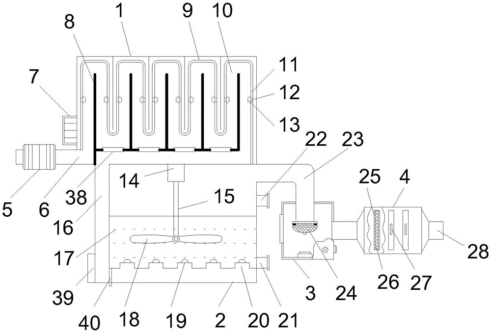
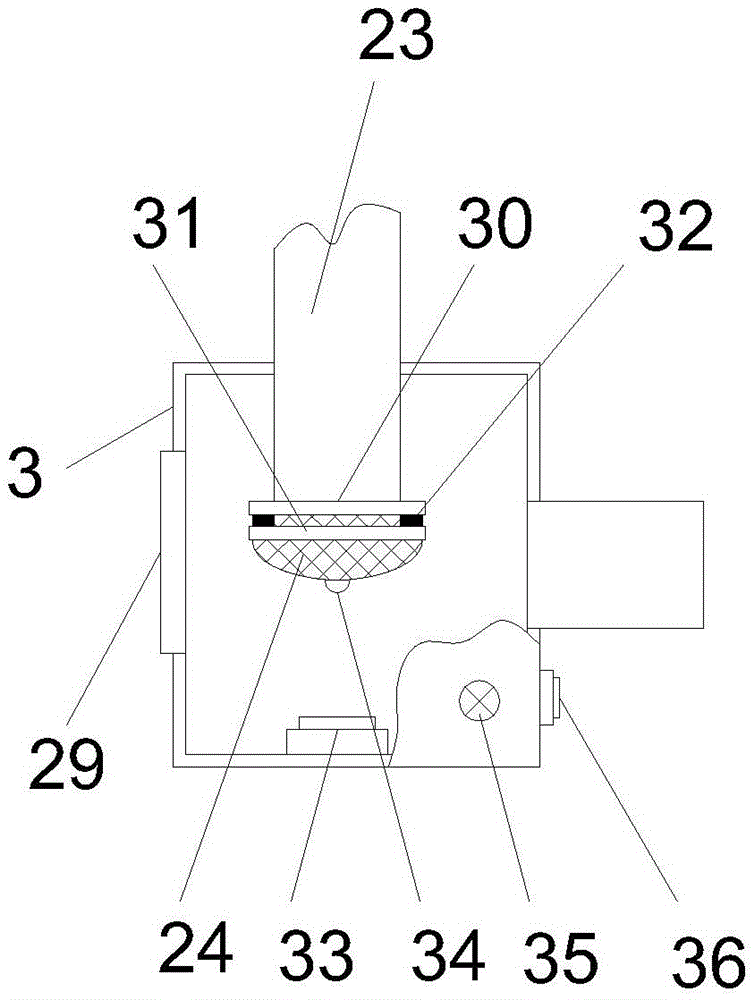
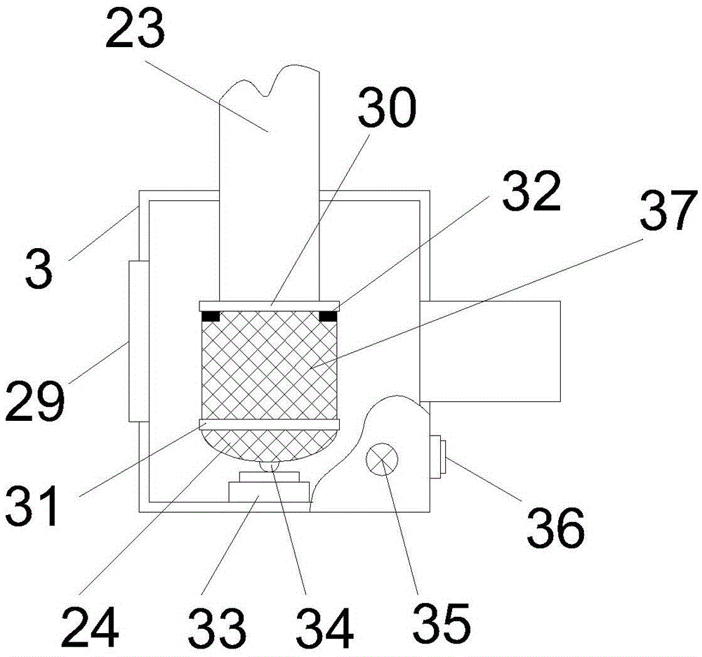
[0018] see Figure 1~3 , in an embodiment of the present invention, an industrial waste gas high-efficiency treatment device includes an electrostatic precipitator box 1, a cleaning and dust removal box 2, and a drying device. The top is provided with an electrostatic precipitator component, which is an adsorption plate 9 that protrudes downwards in a wave shape and is used to realize electrostatic precipitation. A built-in slide rail 11 is arranged on the in...


PUM


Abstract

The invention discloses an efficient treatment device for industrial waste gas. The efficient treatment device comprises an electric dust removal tank, a cleaning dust removal tank and a drying device, wherein a plurality of vertical partition boards are arranged at the bottom of the electric dust removal tank, an electric dust removal assembly is arranged at the top of the electric dust removal tank and adopts an adsorption plate which bulges downwards, is in a wavy shape and is used for realizing electric dust removal, the adsorption plate is connected with an electric dust removal device circuit fixed on the outer side of the electric dust removal tank, an internal slide rail is arranged on the inner side surface of the adsorption plate, a plurality of sliding motors are glidingly connected onto the internal slide rail, cleaning sliders are arranged on the sliding motors, bumps of the adsorption plate and the vertical partition boards are matched to form an S-type electric dust removal channel, the left side of the electric dust removal channel is communicated with a gas inlet pipe, and a pretreatment filtering device is arranged on the gas inlet pipe. The efficient treatment device has the advantages that the structure is simple, the waste gas treatment effect is good, the occupied area and space are small, and inside of the dust removal channel can be cleaned in real time.

Description

technical field [0001] The invention relates to the technical field of environmental protection equipment, in particular to a high-efficiency treatment device for industrial waste gas. Background technique [0002] At present, environmental protection work is the focus of everyone's attention. Regardless of the current environment or the living environment for future generations, environmental protection awareness is the consensus of human beings in the world today. Therefore, relevant laws and regulations have been formulated in various countries, and the country also has relevant regulations and standards for exhaust emissions. . Among them, the processing environment of factories has always been a hidden pain in my country's manufacturing industry. A large number of manufacturing workers often suffer from various occupational diseases when they reach a certain working age, such as tinnitus, noise-induced deafness, pneumoconiosis, dermatitis, and electro-optic ophthalmia....

Claims


Application Information

Patent Timeline
IPC IPC(8): B01D50/00B01D46/30B01D46/52B01D47/02
CPCB01D46/0086B01D46/30B01D46/521B01D47/021B01D50/00B01D2247/10B01D2265/06B01D2267/40
Inventor 梁小利
Owner GUODIANKANGNENG TECH CO LTD
Learn More