
Fixed-gap tooth-free roller-couple grinder

A pulverizer and crushing mechanism technology, applied in the direction of grain processing, etc., can solve the problems of uneven material particle size, gear wear, loud noise, etc., and achieve the effect of increasing service life, improving production efficiency, and avoiding efficiency loss

Inactive Publication Date: 2016-06-15
SHANDONG ACADEMY OF AGRI MACHINERY SCI
View PDF8 Cites 2 Cited by
  • Summary
  • Abstract
  • Description
  • Claims
  • Application Information

AI Technical Summary

Problems solved by technology

However, the traditional roller mill has the following defects: 1. The adjustment mechanism of the grinding roller is unreasonable
In order to protect the grinding rollers of the traditional double-roll pulverizer, it is necessary to ensure that the gap between the two paired grinding rollers has a large elastic adjustment space when crushing materials, so that when encountering materials with large shapes and high hardness, the movable grinding rollers will If they are squeezed apart, there will be a large gap between the two grinding rollers, and the crushing work is in an abnormal state, resulting in extremely uneven particle size of the material, poor crushing effect, and when the movable grinding roller is reciprocally adjusted, it will also generate large noise; 2. The transmission structure is unreasonable
The traditional double-roll pulverizer adopts gear transmission. When the double-roll pulverizer is working normally, the gap between the paired grinding rollers is constantly changing, and the transmission gears are respectively fixed on the two grinding rollers, resulting in constant changes in the center distance between the two gears. During the normal crushing process, the two gears are always in an abnormal meshing state, and the meshing teeth are constantly sliding during the rotation process, which not only causes abnormal wear of the gears, affects the transmission efficiency and service life of the gears, but also produces great transmission noise.

Method used


Image

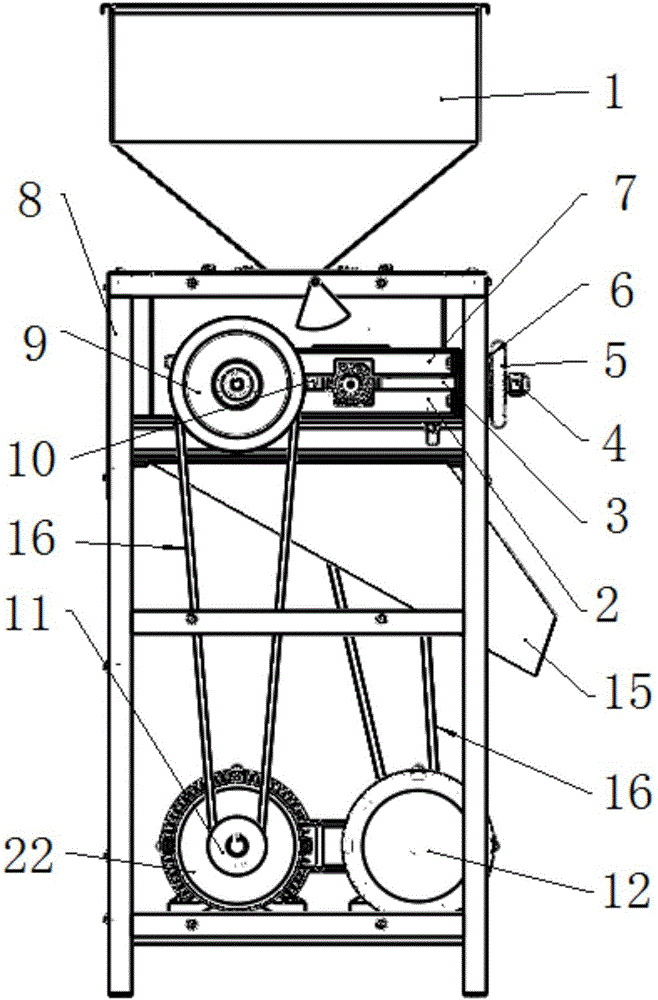
  • Fixed-gap tooth-free roller-couple grinder
  • Fixed-gap tooth-free roller-couple grinder
  • Fixed-gap tooth-free roller-couple grinder

Examples


Embodiment Construction

[0021] The present invention will be further described below in conjunction with the accompanying drawings and embodiments.

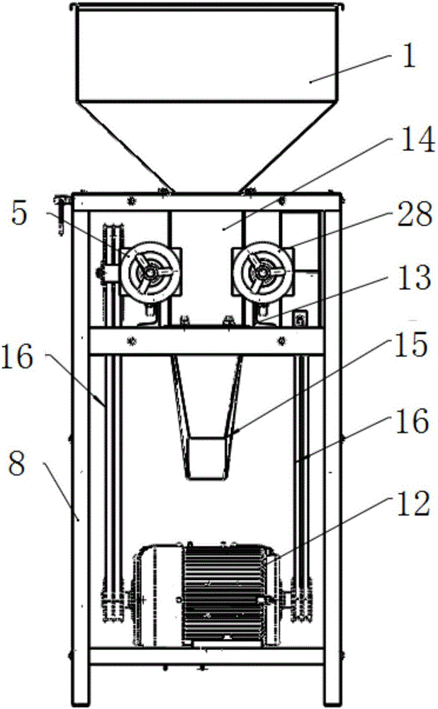
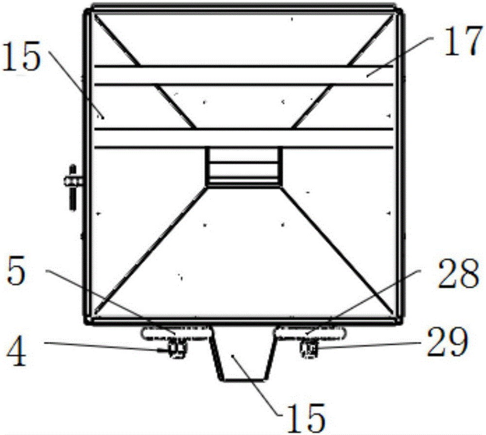
[0022] like Figure 1-Figure 2 As shown in the figure, the fixed-gap free tooth-to-roll pulverizer consists of a feeding hopper 1 and a discharging hopper 15, a grinding roller I18 and a grinding roller II20, etc. The feeding hopper 1 is installed above the frame 8. The transmission mode is that the motor I22 drives the grinding roller I18 to rotate through the pulley I9, and the motor II12 drives the grinding roller II20 to rotate through the pulley II21. The system where the grinding roller I18 is located and the system where the grinding roller II20 is located are two. The independent transmission mechanism does not interfere with each other.

[0023] The gap between the grinding roller I18 and the grinding roller II20 before pulverization is adjustable, and the gap between the grinding roller I18 and the grinding roller II20 is jointly adjusted by ...


PUM


Abstract

The invention discloses a fixed-gap tooth-free roller-couple grinder. The fixed-gap tooth-free roller-couple grinder comprises a rack. A crushing mechanism is fixed to the rack. The top of the crushing mechanism communicates with a feeding hopper, and the bottom of the crushing mechanism communicates with a discharging hopper. The crushing mechanism comprises a roller couple including a first grinding roller and a second grinding roller which are arranged in parallel, and the part between the first grinding roller and the second grinding roller crushes materials. The end of the first grinding roller and the end of the second grinding roller are placed between a bearing upper groove guide rail and a bearing lower groove guide rail through bearing blocks. An elastic element is arranged between the bearing block at the end of the first grinding roller and the bearing block at the end of the second grinding roller. A distance adjusting and positioning device is arranged on the outer side of the bearing block of the first grinding roller or the outer side of the bearing block of the second grinding roller and adjusts and fixes a gap between the first grinding roller and the second grinding roller. In the crushing process, the gap between the first grinding roller and the second grinding roller is kept unchangeable. According to the grinder, the fixed-gap crushing work of the materials can be achieved, tooth-free transmission can be achieved, and the grinder is suitable for the crushing work of dry type materials.

Description

technical field [0001] The invention relates to a powder processing machine, in particular to a fixed-gap free-tooth-roller pulverizer. Background technique [0002] Due to its simple structure and easy manufacture, the roller mill has been widely used in the pharmaceutical, chemical, beer, food and food additives industries. But the traditional roller mill has the following defects: 1. The adjustment mechanism of the grinding roller is unreasonable. In order to protect the grinding rollers of the traditional roller mill, it is necessary to ensure that the gap between the paired two grinding rollers has a large elastic adjustment space when crushing materials, so that when encountering materials with larger shapes and higher hardness, the movable grinding rollers will It is squeezed apart, there is a large gap between the two grinding rollers, and the crushing work is in an abnormal state, resulting in extremely uneven particle size of the material, poor crushing effect, an...

Claims


Application Information

Patent Timeline
Patent Type & Authority Applications(China)
IPC IPC(8): B02C4/02B02C4/42B02C4/32B02C23/04
CPCB02C4/02B02C4/32B02C4/42B02C23/04
Inventor 孔凡祝李寒松慈文亮贺晓东贾振超张宗超李青李英治陈宁王斌齐雯
Owner SHANDONG ACADEMY OF AGRI MACHINERY SCI
Learn More