Eureka AIR delivers breakthrough ideas for toughest innovation challenges, trusted by R&D personnel around the world.

Spinning wheel used for machining wind tunnel flange

A technology of spinning wheels and flanges, which is applied in the field of metal plastic forming machinery, can solve the problems that the plane perpendicular to the center line of the air cylinder cannot be achieved, the surface flatness of the bell mouth-shaped air cylinder is unqualified, and the processing accuracy of the workpiece is low, etc., to achieve Light weight, eliminate rough smooth, simple structure effect

Inactive Publication Date: 2016-06-15
WEIHAI CREDITFAN VENTILATOR
View PDF0 Cites 1 Cited by
  • Summary
  • Abstract
  • Description
  • Claims
  • Application Information

AI Technical Summary

Problems solved by technology

[0002] As we all know, the trumpet-shaped air cylinder is composed of a trumpet forming surface and a flange plane. When spinning a traditional bell-mouth air cylinder, the lower spinning wheel and the upper spinning wheel are usually used to plastically deform the horn shape of the air cylinder. The above-mentioned bottom spinning wheel is usually composed of a cylinder in the middle and hemispheres at both ends of the cylinder, and the two ends of the cylinder are respectively connected with the hemispheres, so that the molding surface of the horn produced by spinning is smooth and stable, and the hemispheres The end surface of the body is provided perpendicular to the centerline of the lower spinning wheel, and the center of the lower spinning wheel is provided with a mounting hole. On the centerline of the lower spinning wheel, during the plastic forming process, the lower spinning wheel is in three-point contact with the fan cylinder, the middle point is at the same point as the upper wheel of the fan tube flange, and the other two points are in contact with the fan tube flange, which are in contact with the fan cylinder. The relative position of the flange gradually increases from the inside to the outside, and the distance between the two points at the outer end gradually increases, while the relative position between the middle point and the flange gradually decreases, which causes the end face of the fan flange to show a flange rebound surface, which leads to the air tube method. The blue is arc-shaped and cannot reach a plane perpendicular to the centerline of the fan cylinder; secondly, because the axis of the lower spinning wheel is difficult to be parallel to the central axis of the base during the spinning process, the intersection of the cylinder and the hemisphere is in the spinning position. When the horn forming surface is pressed, an obvious spinning edge line is formed, which makes the flatness of the surface of the bell-shaped air duct unqualified
[0003] At present, in order to solve the rebound of the flange surface during the spinning process, usually after the horn forming surface of the air cylinder is finished spinning, the above-mentioned lower spinning wheel is removed, and a flange-forming lower spinning wheel is reinstalled. One end face of the flange forming lower spinning wheel is perpendicular to the axis of the flange forming lower spinning wheel, so that the upper spinning wheel and the end face of the flange forming lower spinning wheel work together to make the horn-shaped air cylinder Its shortcomings are: cumbersome processing, inconvenient loading and unloading, low work efficiency, and low machining accuracy of workpieces.

Method used


Image

  • Spinning wheel used for machining wind tunnel flange
  • Spinning wheel used for machining wind tunnel flange
  • Spinning wheel used for machining wind tunnel flange

Examples


Embodiment Construction

[0014] Combined with the accompanying drawings below ] The present invention further illustrates:

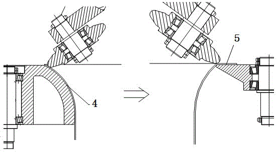
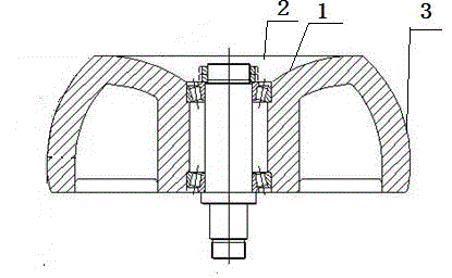
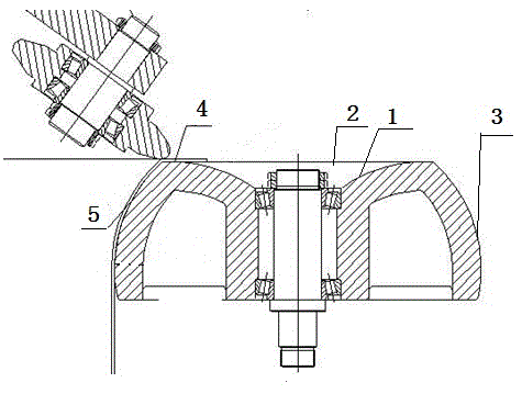
[0015] As shown in the attached figure, a spinning wheel for processing the flange of the blower is provided with a bottom spinning wheel, and the center of the bottom spinning wheel is provided with a mounting hole, which is characterized in that the upper end surface of the bottom spinning wheel It is an arc-shaped surface 1. The arc-shaped surface 1 gradually deviates from the horizontal plane from the outer end to the center and extends downward to the installation hole in an arc shape, so that the upper end surface is concave 2, which is beneficial to ensure that the spinning method During the spinning process, the flange surface is plastically rebounded to the horizontal position, so that the flange surface of the bell mouth-shaped fan cylinder and the horn forming surface are integrally formed, which greatly facilitates the processing, and also improves the work efficienc...


PUM


Abstract

The invention relates to the technical field of metal plastic forming machines, in particular to a spinning wheel used for machining a wind tunnel flange. The spinning wheel is provided with a lower spinning wheel body, and an installation hole is formed in the center of the lower spinning wheel body. The spinning wheel is characterized in that the upper end surface of the lower spinning wheel body gradually deviates from a horizontal plane from the outer end to the center and extends to the installation hole in an arc downward mode, so that the upper end surface is concaved; the effect that a flange surface subjected to spinning bounds back to the horizontal position due to plasticity in the spinning process is guaranteed; and the flange surface of a horn-mouth-shaped wind tunnel and a horn forming surface are integrally formed, machining is greatly facilitated, and the work efficiency and machining accuracy of workpieces are greatly improved. Due to the structure, the spinning wheel used for machining the wind tunnel flange has the advantages of being simple in structure, convenient to machine, high in machining accuracy, light in weight, low in cost, short in machining period, high in work efficiency, attractive in appearance and the like.

Description

technical field [0001] The invention relates to the technical field of metal plastic forming machinery, in particular to a spinning wheel used for processing air cylinder flanges. Background technique [0002] As we all know, the trumpet-shaped air cylinder is composed of a trumpet forming surface and a flange plane. When spinning a traditional bell-mouth air cylinder, the lower spinning wheel and the upper spinning wheel are usually used to plastically deform the horn shape of the air cylinder. The above-mentioned bottom spinning wheel is usually composed of a cylinder in the middle and hemispheres at both ends of the cylinder, and the two ends of the cylinder are respectively connected with the hemispheres, so that the molding surface of the horn produced by spinning is smooth and stable, and the hemispheres The end surface of the body is provided perpendicular to the centerline of the lower spinning wheel, and the center of the lower spinning wheel is provided with a moun...

Claims


Application Information

Patent Timeline
Patent Type & Authority Applications(China)
IPC IPC(8): B21D22/16
Inventor 孔宪良殷庆锋辛驰
Owner WEIHAI CREDITFAN VENTILATOR
Why Eureka
Eureka Blog
Learn More