
Automobile wheel inertial energy recycling device and method

A technology of inertial energy and recovery devices, applied in control devices, vehicle components, transportation and packaging, etc., can solve problems such as the influence of transmission efficiency, long transmission chains, complex structures of energy recovery devices, etc., and achieve high transmission efficiency and short transmission chains Effect

Active Publication Date: 2016-06-15
JIANGSU UNIV
View PDF5 Cites 11 Cited by
  • Summary
  • Abstract
  • Description
  • Claims
  • Application Information

AI Technical Summary

Problems solved by technology

It can be known from dynamics that the inertial energy of a wheel depends on its speed and mass. Due to the limitation of the speed of the car, the speed of the wheel shaft cannot be very high, generally below 1000 revolutions per minute. The inertial energy generated cannot be released and recovered quickly, which affects the energy recovery rate to a certain extent
In addition, since the transmission part is installed on the wheel shaft, this will inevitably increase the moment of inertia of the rotating part. When the car starts or accelerates, this part of the increased moment of inertia will also consume additional driving energy of the car engine.
[0005] At present, there are many energy recovery devices with complex structures, and they basically use indirect transmission, and the transmission chain is long, which has a certain impact on the transmission efficiency.

Method used


Image

  • Automobile wheel inertial energy recycling device and method
  • Automobile wheel inertial energy recycling device and method
  • Automobile wheel inertial energy recycling device and method

Examples


Embodiment Construction

[0031] The present invention will be further described below in conjunction with the accompanying drawings and specific embodiments, but the protection scope of the present invention is not limited thereto.

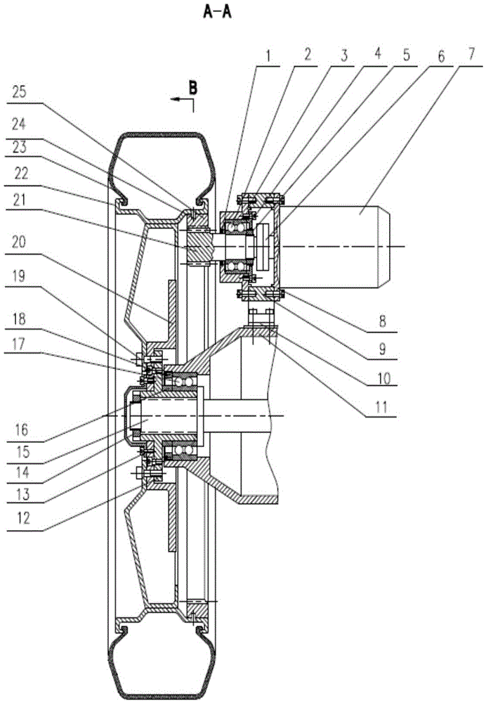
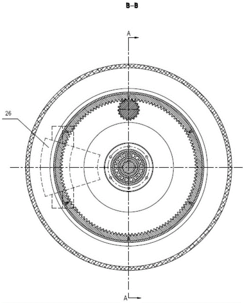
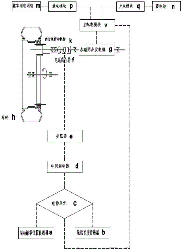
[0032] Such as figure 1 , figure 2 As shown, the vehicle wheel inertial energy recovery device of the present invention includes an internal gear transmission mechanism, an electromagnetic clutch assembly, a generator assembly, a sensor assembly, an electronic control unit, a main power distribution module, a discharge module, and a charging module.

[0033] The internal gear transmission mechanism includes an internal gear insert 25, a double row angular contact bearing 2, a bearing seat 3, a bearing gland 4, a round nut 5, and a gear shaft 21, and the internal gear insert is fixed on one end of the gear shaft. And its outer surface is fixed on the inner ring of the wheel hub, the bearing seat 3 is fixed on the rear axle body 11, the double row angular contact bearing ...


PUM


Abstract

The invention provides a device and method for recovering the inertial energy of automobile wheels, belonging to the fields of automobile energy saving and emission reduction and new energy electric vehicles. The invention adds a fixed internal gear insert on the inner ring of the automobile wheel hub. When the automobile wheel rotates, the power increases through the internal gear transmission mechanism and directly drives the permanent magnet synchronous generator to generate electricity, which is generated by the brake pedal sensor and the tire speed sensor. The signal controls the opening and closing of the electromagnetic clutch, which directly drives the permanent magnet synchronous generator to generate electricity. At the moment of braking and deceleration of the car, it can quickly release and recover the inertial energy of the car wheels in large quantities, and provide power to the battery or the power network of the whole vehicle. The device has the advantages of simple structure, small volume, high energy recovery rate, good reliability, low manufacturing cost, and certain technical and economic feasibility.

Description

technical field [0001] The invention relates to a device and method for recovering the inertial energy of automobile wheels, and belongs to the technical fields of automobile energy saving and emission reduction and new energy electric vehicles. Background technique [0002] When the car is running on the road, at least one-third of the energy of the fuel engine or the driving motor of the electric car is used to overcome the rolling resistance of the car wheels, and the resistance of this part is proportional to the mass of the car itself and the speed of driving . When a car brakes, coasts or decelerates, this creates a huge amount of inertial energy. With the shortage of energy and the increasing attention to the environment in the world, how to effectively recover this part of inertial energy not only has certain economic benefits, but also has certain social significance. [0003] Attempts have long been made to store a car's inertial energy indirectly by installing a...

Claims


Application Information

Patent Timeline
IPC IPC(8): B60K17/02B60K17/04B60R16/023B60R16/03
CPCY02T10/92B60K17/02B60K17/04B60R16/0231B60R16/0307
Inventor 汪若尘邵凯叶青陈龙江浩斌
Owner JIANGSU UNIV
Learn More