Natural gas engine colliding oil and gas separator

A technology of oil and gas separator and engine, which is applied in the direction of engine components, machines/engines, mechanical equipment, etc. It can solve the problems of low oil and gas separation rate, large resistance, and low oil and gas separation efficiency, so as to improve separation efficiency, facilitate cleaning and maintenance, Improvement of impact separation effect

Active Publication Date: 2018-05-29
WEICHAI XIGANG NEW ENERGY POWER
View PDF8 Cites 0 Cited by
  • Summary
  • Abstract
  • Description
  • Claims
  • Application Information

AI Technical Summary

Problems solved by technology

[0003] At present, the oil and gas separators of most engines adopt two structures of labyrinth or centrifugal separation. The separation methods of the above two structures generally have the phenomenon of low oil and gas separation efficiency, and there is also the problem of oil and gas backflow. When oil and gas backflow occurs , will cause the resistance in the process of gas separation to be too large, and then cause the oil-gas separation rate to decrease, thus affecting the normal operation of the engine

Method used


Image

  • Natural gas engine colliding oil and gas separator
  • Natural gas engine colliding oil and gas separator
  • Natural gas engine colliding oil and gas separator

Examples


Embodiment Construction

[0020] The present invention will be further described below in conjunction with the drawings and embodiments. In the following detailed description, only certain exemplary embodiments of the present invention are described by way of illustration. Needless to say, those of ordinary skill in the art can realize that the described embodiments can be modified in various ways without departing from the spirit and scope of the present invention. Therefore, the drawings and descriptions are illustrative in nature and are not used to limit the scope of protection of the claims.

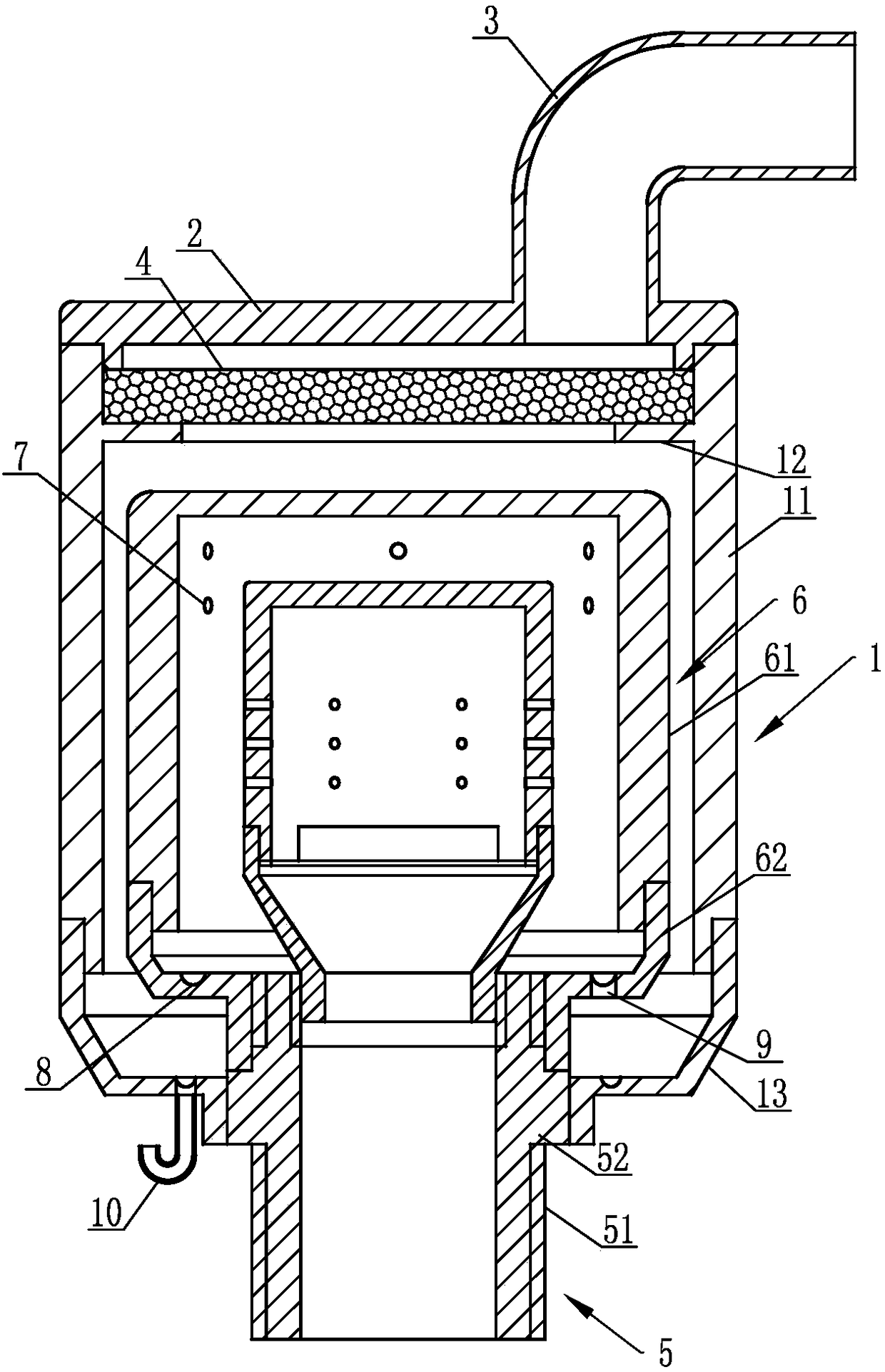
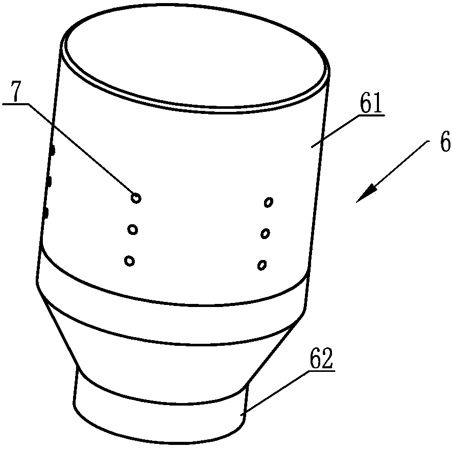
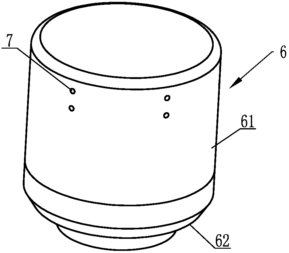
[0021] Such as figure 1 , figure 2 , image 3 , Figure 4 with Figure 5 As shown, the collision-condensing oil-gas separator of a natural gas engine includes an outer separation sleeve 1, a sleeve end cover 2 is sealed at the top of the outer separation sleeve 1, and an exhaust pipe 3 is provided on the sleeve end cover 2. The top end of the outer separation sleeve 1 is provided with a filter element 4, the...


PUM


Abstract

The invention discloses a colliding condensation type oil-gas separator for a natural gas engine. The colliding condensation type oil-gas separator comprises an outer release sleeve, a sleeve end cover, an exhaust pipe, a filter element and an air inlet supporting pipe, wherein at least two layers of inner release sleeves which are separately connected with the air inlet supporting pipe sequentially are sleeved with the outer release sleeve; oil-gas jetting holes are formed in the circumferential walls of the inner release sleeves; oil accumulating circular grooves are separately formed in the lower ends of all the inner release sleeves positioned outside the innermost layer of inner release sleeve and the lower end of the outer release sleeve; oil guiding holes are separately formed in the corresponding oil accumulating circular grooves in a penetrating way; an oil accumulating choke tube communicates with the oil guiding hole positioned in the outer release sleeve; an oil-gas mixture can form a colliding condensation phenomenon by using all the oil-gas jetting holes; in addition, by using a separating action of a filter element, the oil-gas mixture is filtered and separated for multiple times; the sleeve end cover can be opened for facilitating cleaning and maintenance at fixed period; accumulated oil is exported outwards layer by layer for collecting by using the oil accumulating circular grooves and the oil guiding holes; and by using the oil accumulating choke tube, the reflow of the mixed oil and gas can be avoided, thereby guaranteeing the colliding condensation effect and improving the separating rate of oil and gas.

Description

Technical field [0001] The invention relates to the technical field of engine parts, in particular to an oil-gas separator used on a natural gas engine. Background technique [0002] In order to prevent engine oil from entering the air intake system of the vehicle, causing pipeline pollution and deterioration of engine combustion performance, resulting in a decrease in engine emissions, oil and gas separators are installed on each motor vehicle. The oil and gas separator is part of the exhaust gas circulation system. It is connected with an independent pipeline. Its function is to decompose the oil vapor in the oil pan and the water vapor escaping from the combustion chamber, and the separated oil film flows along the pipe wall. To the oil pan, the filtered steam enters the engine to form a closed loop or is directly discharged to reduce the air pollution rate. [0003] At present, most of the engine's oil and gas separators use two kinds of structures: labyrinth or centrifugal se...

Claims


Application Information

Patent Timeline
Patent Type & Authority Patents(China)
IPC IPC(8): F01M13/04
CPCF01M13/04F01M2013/0061F01M2013/0438
Inventor 孔龙王景丽李玉帅李风芹
Owner WEICHAI XIGANG NEW ENERGY POWER
Why Eureka
Try Eureka