Discharging device in material cylinder

A technology of unloading device and barrel, which is applied in the direction of charge, furnace, charge composition/state, etc., can solve the problems of unloading of sintered ore and unloading as required, achieving simple structure, increasing unloading points, The effect of increasing the uniformity of discharge

Active Publication Date: 2016-06-15
TIANJIN ZHENGYUANHE TECH DEV CO LTD
View PDF3 Cites 2 Cited by
  • Summary
  • Abstract
  • Description
  • Claims
  • Application Information

AI Technical Summary

Problems solved by technology

[0004] Judging from the existing devices and methods for recovering waste heat from sinter, there is a problem that the cooled sinter cannot be unloaded evenly and cannot be unloaded as required

Method used


Image

  • Discharging device in material cylinder
  • Discharging device in material cylinder
  • Discharging device in material cylinder

Examples


Embodiment Construction

[0030] Hereinafter, the unloading device in the cartridge as the present invention will be described based on the drawings.

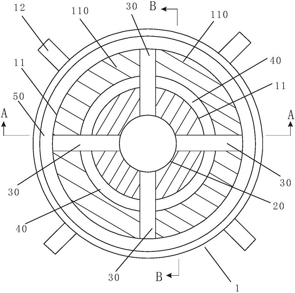
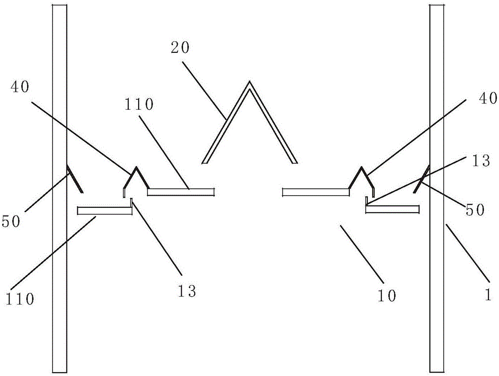
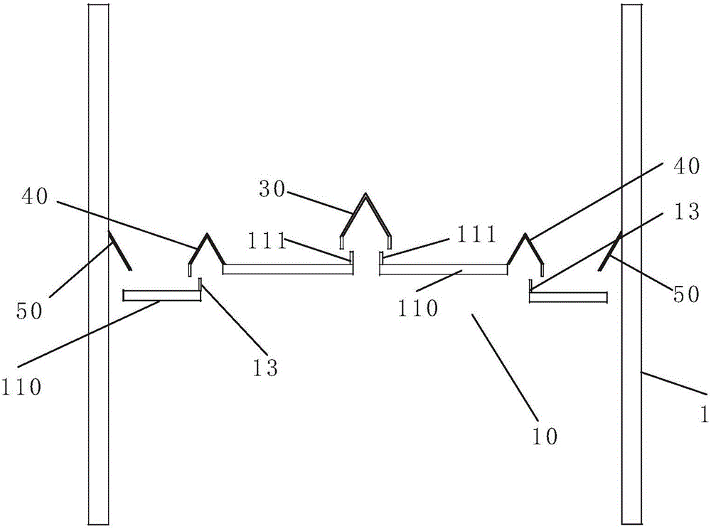
[0031] figure 1 It is a schematic plan view showing the discharge device in the cartridge of the present invention. figure 2 It is a schematic cross-sectional view of A-A showing the discharge device in the cartridge of the present invention. image 3 It is a schematic cross-sectional view of B-B showing the discharge device in the barrel of the present invention. Figure 4 It is a B-B cross-sectional schematic diagram showing the discharge device in the barrel of the present invention without the first baffle plate and the second baffle plate. Figure 5 It is a B-B cross-sectional schematic diagram showing another embodiment of the unloading device in the cartridge of the present invention without the first baffle plate and the second baffle plate. Image 6 It is a schematic cross-sectional view A-A showing another embodiment of the unloading device in the ...


PUM


Abstract

The invention discloses a discharging device in a material cylinder, which can uniformly discharge materials as required. The discharging device comprises a discharging plate mechanism, a central material cover, radial leakage-proof covers and a side plate, which are connected with the material cylinder respectively, wherein the discharging plate mechanism is mounted on a support member inside the material cylinder, covers a material channel of the material cylinder, and comprises an annular discharging plate and reciprocating drivers; the annular discharging plate is formed by splicing a plurality of sectorial moving plate units, and each moving plate unit is connected with the material cylinder through the corresponding reciprocating driver; the central material cover is tapered, and a through hole in the center of the annular discharging plate is covered with the central material cover; the side plate obliquely extends downwards towards the axis of the material cylinder from the wall of the material cylinder, and a gap between the annular discharging plate and the wall of the material cylinder is covered with the side plate; each radial leakage-proof cover covers a gap between the adjacent moving plate units, and the top end of each radial leakage-proof cover is in a left-turned E shape.

Description

Technical field [0001] The invention relates to a discharge device in a material barrel. Background technique [0002] At present, steel has become an indispensable material in people's life and production, and the steel used in modern life is mainly obtained from iron ore. In the process of smelting, in order to fully react the iron ore to produce as much steel as possible, it is usually necessary to crush and screen the iron ore. Since the crushed ore powder is not easy to be smelted in a furnace, it needs to be sintered into a block. , Spherical shape, and then loaded into the furnace for smelting. [0003] The existing sintering process in the iron and steel industry includes batching, sintering, cooling, screening and other processes. Among them, the cooling process after the completion of the sintering process mainly uses process equipment such as ring cooling and band cooling to make the material temperature of the sintered ore change from 700 ℃ Decrease to 100 to 180°C. ...

Claims


Application Information

Patent Timeline
Patent Type & Authority Applications(China)
IPC IPC(8): F27D3/00
CPCF27D3/00F27M2001/02F27M2003/04
Inventor 高静涛白银川
Owner TIANJIN ZHENGYUANHE TECH DEV CO LTD
Why Eureka
Try Eureka