
Liquid crystal display panel, manufacturing method thereof and display device comprising liquid crystal display panel

A liquid crystal display panel, display panel technology, applied in nonlinear optics, instruments, optics, etc., can solve the problems of increasing the thickness of the display panel, and the limited effect of converting quantum rods into polarized light, so as to reduce the thickness, improve the utilization rate, The effect of improving the utilization rate

Active Publication Date: 2016-06-15
BOE TECH GRP CO LTD
View PDF4 Cites 17 Cited by
  • Summary
  • Abstract
  • Description
  • Claims
  • Application Information

AI Technical Summary

Problems solved by technology

[0003] To sum up, at present, a quantum rod layer is provided in the polarizing plate to increase the amount of light entering the polarizing layer in the polarizing plate. Although the utilization rate of the backlight source can be improved to a certain extent, the quantum rod layer still needs to be installed. , polarizing layer and backlight, which increases the thickness of the display panel, and the effect of quantum rods on converting unpolarized lines into polarized light is limited

Method used


Image

  • Liquid crystal display panel, manufacturing method thereof and display device comprising liquid crystal display panel
  • Liquid crystal display panel, manufacturing method thereof and display device comprising liquid crystal display panel
  • Liquid crystal display panel, manufacturing method thereof and display device comprising liquid crystal display panel

Examples


Embodiment Construction

[0036] The technical solutions in the embodiments of the present invention will be clearly and completely described below in conjunction with the accompanying drawings in the embodiments of the present invention. Obviously, the described embodiments are only a part of the embodiments of the present invention, not all the embodiments. Based on the embodiments of the present invention, all other embodiments obtained by those of ordinary skill in the art without creative work shall fall within the protection scope of the present invention.

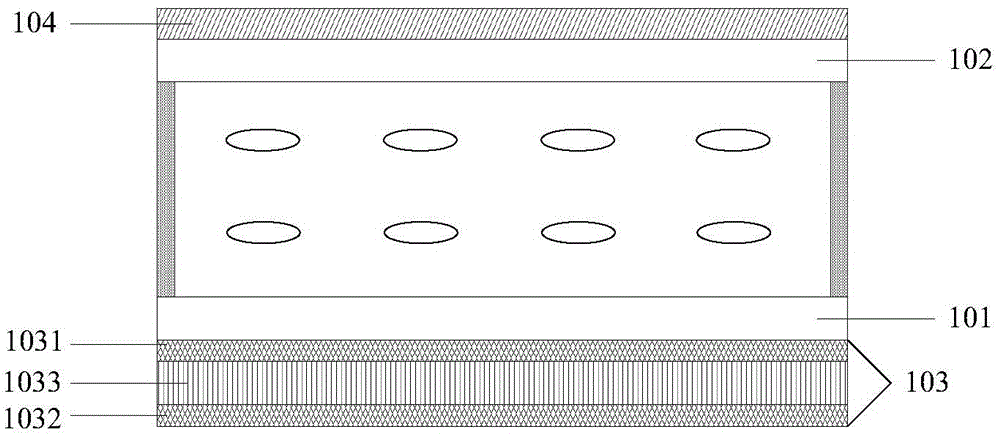
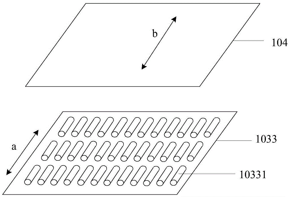
[0037] Such as figure 1 As shown, it is a schematic structural diagram of a liquid crystal display panel provided by an embodiment of the present invention, including: an array substrate 101 and a counter substrate 102 arranged oppositely, arranged on the side of the array substrate 101 away from the counter substrate 102 and capable of emitting lines A polarizing structure 103 for polarized light; a polarizing plate 104 disposed on the counter s...


PUM

PropertyMeasurementUnit
visible light transmittanceaaaaaaaaaa

Abstract

The invention relates to a liquid crystal display panel, a manufacturing method thereof and a display device comprising the liquid crystal display panel, and aims to solve the problem that although the utilization rate of a backlight source is increased by arranging a quantum rod layer in a polarizing plate, the thickness of a display panel is increased, and moreover a quantum rod has a limited effect of light conversion. The liquid crystal display panel comprises an array substrate, an opposite substrate, a polarized light structure and a polarizing film, wherein the polarized light structure is arranged on one side, back on to the opposite substrate, of the array substrate, and is capable of emitting linearly polarized light; the polarizing film is arranged on the opposite substrate; the polarized light structure comprises a first electrode layer, a second electrode layer and a quantum rod layer positioned between the first electrode layer and the second electrode layer; the quantum rod layer is adopted to emit linearly polarized light of which the polarization direction is parallel to the absorbing axis of the polarizing film when voltage is loaded. As the polarized light structure in the liquid crystal display panel can emit linearly polarized light, a backlight source and a lower polarizing film are not needed, and thus the thickness of the display panel can be reduced; meanwhile the emitted linearly polarized light can directly enter the electrode layers, a liquid crystal layer and the like, so that the utilization rate of light can be increased.

Description

Technical field [0001] The present invention relates to the field of display panels, in particular to a liquid crystal display panel, a manufacturing method thereof and a display device. Background technique [0002] At present, the polarizer matched with the liquid crystal display panel usually adopts an absorbing polarizer. When the light emitted by the backlight passes through the polarizer, the component in the direction of the absorption axis of the polarizer will be absorbed and cannot pass through. Therefore, the The light transmittance of the polarizer to the backlight can only reach 50% or less theoretically, and the utilization rate of the backlight is quite low, resulting in a waste of energy. In the prior art, a polarizing plate provided with a layer of quantum rods is proposed. After the quantum rods can absorb unpolarized light in the long axis direction, they can excite polarized light with a longer wavelength than the original incident light source. The quantum e...

Claims


Application Information

Patent Timeline
Patent Type & Authority Applications(China)
IPC IPC(8): G02F1/13357
CPCG02F1/133602G02F1/13362G02F2202/108G02F1/133528G02F1/133553G02F1/134309G02F1/13439G02F2202/36G02F2203/05G02F1/133614
Inventor 杨久霞徐文艳
Owner BOE TECH GRP CO LTD
Learn More