Visual modeling method for distributed simulation platform

A technology of distributed simulation and modeling method, applied in the field of real-time distributed simulation platform, can solve the problems of low development efficiency, long development cycle, poor reconfiguration, etc.

Active Publication Date: 2016-06-15
10TH RES INST OF CETC
View PDF2 Cites 46 Cited by
  • Summary
  • Abstract
  • Description
  • Claims
  • Application Information

AI Technical Summary

Problems solved by technology

[0005] The purpose of the present invention is to solve the disadvantages that a large number of mapping tables and configuration files will be generated in the process of completing the reconstruction of the above-mentioned prior art, which cannot meet the object-oriented design idea, and the semantics are vague, which increases the design burden and complexity of the user. , proposes a visual modeling method that can reduce the development complexity of all nodes in distributed simulation without calling each model resource, without complex function tailoring or secondary development of the software architecture of the distributed simulation platform containing sub-nodes. Overcome the problems of unclear module boundaries, high module coupling, poor module scalability, difficult module cutting, poor reconfiguration, long development cycle, and low development efficiency in the prior art

Method used


Image

  • Visual modeling method for distributed simulation platform
  • Visual modeling method for distributed simulation platform
  • Visual modeling method for distributed simulation platform

Examples


Embodiment Construction

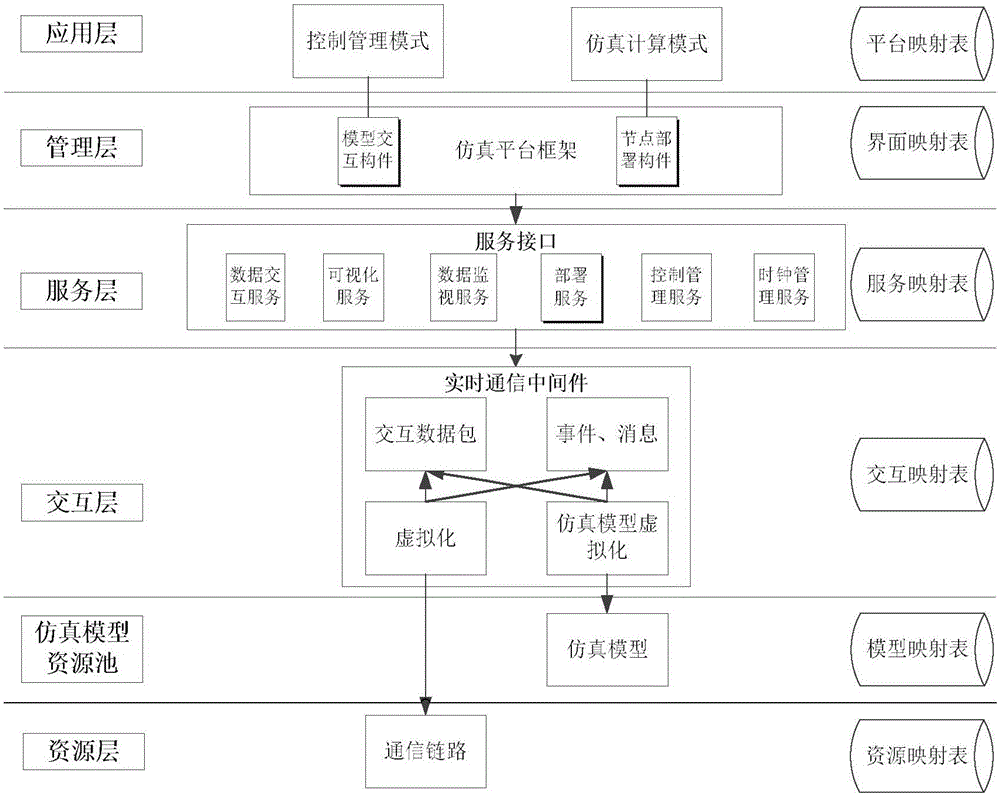
[0032] See figure 1 figure 2 . According to the present invention, a simulation platform framework and visual modeling related components are created, distributed simulation deployment is performed in a visual manner, and the simulation platform framework is divided into application layer, management layer, service layer, interaction layer, resource layer and Simulation model resource pool; and each level has related models and components, and corresponds to a mapping table to describe the attributes, functions, and parameter information of the models and components of this level, and each view window of each level is relatively independent. The level only provides interfaces and cannot be accessed. The next level is accessed through the next level interface. The data interaction between each model resource is realized through the service interface in the service layer; then the sub-nodes are divided into two modes: control management and simulation calculation , Simulation mo...


PUM


Abstract

The invention proposes a visual modeling method for a distributed simulation platform and aims to provide a visual modeling method capable of lowering the development complexity of all nodes of distributed simulation. The method is realized by the following technical scheme: creating a simulation platform framework and visual modeling related components; performing distributed simulation deployment visually; dividing the simulation platform framework into an application layer, a management layer, a service layer, an interaction layer, a resource layer and a simulation model resource pool from top to bottom, wherein the management layer comprises a model interaction component and a node deployment component; generating an icon arranged in the simulation model resource pool by the model interaction component according to an interface attribute of a simulation model; seamlessly connecting logic deployment and physical deployment of simulation system nodes; automatically generating corresponding software interfaces and corresponding service components by simulation sub-nodes participating in distributed simulation through a node deployment graph; and performing visual modeling in a model interaction view to construct a visual model convenient for a user to design the simulation model interaction view.

Description

Technical field [0001] The present invention relates to a distributed simulation technology application field, a general design architecture used for a reconfigurable real-time distributed simulation platform and an implementation method thereof, especially applicable to the fields of distributed simulation, semi-physical simulation, automated testing, etc. Real-time distributed simulation platform. Background technique [0002] Simulation technology builds a bridge between the objective world and scientific theory, and is considered to be the third important method for understanding and transforming the world after theoretical analysis and scientific experiments. Distributed interactive simulation technology can distribute calculations to multiple hosts, reducing the dependence on the performance of a single computer, and bringing more computing resources to the simulation, while virtual reality technology adds intuitiveness and immersion to the system. Distributed simulation d...

Claims


Application Information

Patent Timeline
Patent Type & Authority Applications(China)
IPC IPC(8): G06F9/455G06F9/44
CPCG06F8/35G06F9/45508G06F9/45558G06F2009/4557
Inventor 谢林杜增
Owner 10TH RES INST OF CETC
Why Eureka
Try Eureka