Multi-condition propulsion performance optimization design method for a composite propeller
A composite material and optimization design technology, applied in calculation, instrumentation, geometric CAD, etc., can solve problems such as imperfect design methods of composite material propellers
- Summary
- Abstract
- Description
- Claims
- Application Information
AI Technical Summary
Problems solved by technology
Method used
Image
Examples
specific Embodiment approach 1
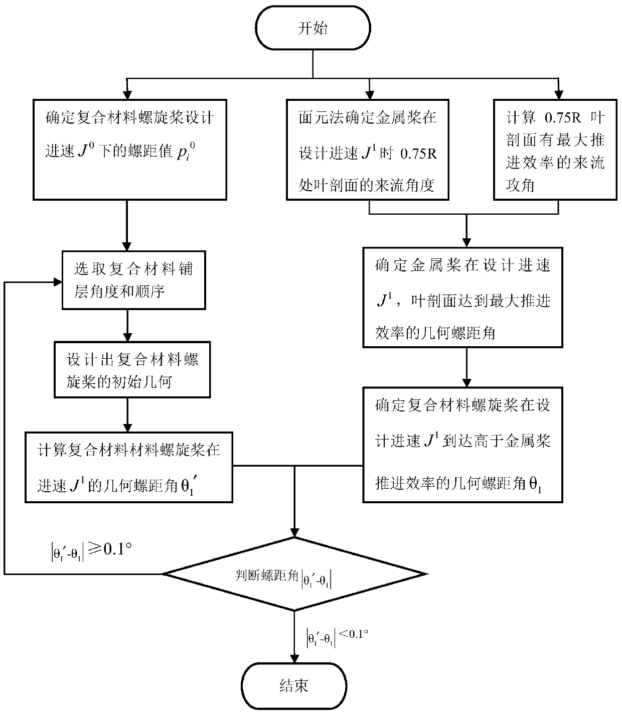
[0024] Specific implementation mode one: combine figure 1 To illustrate this embodiment, a multi-working-condition propulsion performance optimization design method for a composite material propeller in this embodiment is specifically prepared according to the following steps:
[0025] Step 1. Start;
[0026] Step 2. Determine the design speed J of the composite material propeller 0 The pitch value under p i 0 , where i=1,2...n, n is the radial radius number of the composite material propeller, and the value is a positive integer;
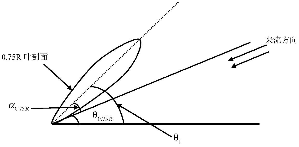
[0027] Step 3. Use the panel method to determine the design speed of the metal propeller at J 1 When , the incoming flow angle θ of the blade section at 0.75R 0 . 75R ;
[0028] Step 4. Calculate the incoming flow attack angle α of the maximum propulsion efficiency of the blade section at 0.75R of the main blade of the metal propeller 0.75R ;
[0029] Step 5. According to Step 3 and Step 4, determine that the design speed of the metal prop...
specific Embodiment approach 2
[0036] Specific embodiment two: the difference between this embodiment and specific embodiment one is: in the said step two, determine the design advance speed J of the composite material propeller 0 The pitch value under p i 0 , where i=1,2...n, n is the number of radial radii of the composite material propeller; the specific process is:
[0037] Taking the geometry of the metal propeller as the basic parameter, the design advance speed of the metal propeller is J 0 , the radial pitch value is p i 0 , where i=1,2...n, n is the radial radius number of the metal propeller; the radial pitch value p of the metal propeller i 0 Determined as the design speed J of the composite material propeller 0 The pitch value under p i 0 (Composite material propeller at the design advance speed of J 0 The pitch value after torsion deformation occurs at p i 0 ).
[0038] Other steps and parameters are the same as those in Embodiment 1.
specific Embodiment approach 3
[0039] Specific embodiment three: the difference between this embodiment and specific embodiment one or two is that in the step three, the panel method is used to determine the metal propeller at a design advance speed of J 1 , the incoming flow angle at the leading edge of the blade section leading edge at 0.75R; the specific process is:
[0040] Based on Green's formula, use the Fortran language to write the metal propeller surface element method program, according to the solution model of the metal propeller velocity field Solve the velocity field 4πV(p) of the metal propeller, and solve the disturbance velocity V(p) of the watershed where the metal propeller is located according to the velocity field 4πV(p) of the metal propeller;
[0041] Among them, p is an arbitrary point in the flow field, V(p) is the disturbance velocity of the water domain where the metal propeller is located, Q is a point on the surface of the propeller, is the disturbance potential, is the velo...
PUM
 Abstract
Description
Claims
Application Information
 - R&D
- Intellectual Property
- Life Sciences
- Materials
- Tech Scout
- Unparalleled Data Quality
- Higher Quality Content
- 60% Fewer Hallucinations
Browse by: Latest US Patents, China's latest patents, Technical Efficacy Thesaurus, Application Domain, Technology Topic, Popular Technical Reports.
© 2025 PatSnap. All rights reserved.Legal|Privacy policy|Modern Slavery Act Transparency Statement|Sitemap|About US| Contact US: help@patsnap.com


