
Filter and transmission zero point adjustment method therefor

A filter and resonator technology, applied in the field of filter transmission zero adjustment, can solve the problems of difficulty, large filter design, low filter processing yield, etc., and achieve the effect of reducing physical size

Active Publication Date: 2016-06-15
UNIV OF ELECTRONICS SCI & TECH OF CHINA
View PDF2 Cites 1 Cited by
  • Summary
  • Abstract
  • Description
  • Claims
  • Application Information

AI Technical Summary

Problems solved by technology

[0004] (1) Most of the coupling realized by using the crossover line is electric field coupling. In order to realize the quasi-elliptic function characteristics of the filter, it is required that the coupled coupling in the main path must be magnetic field coupling, which makes the structure selection of the resonator subject to certain restrictions. limit
[0005] (2) In order to avoid unnecessary additional coupling between the crossover line and unrelated resonators while achieving the desired cross-coupling, it is often necessary to optimize the topology of the filter and use some resonators with very special structures And the special coupling structure, and sometimes the resonators have to be misplaced, which is not conducive to the miniaturization design of the filter
Therefore, it is difficult to achieve strong coupling between resonators by using crossover lines, and it is also difficult to achieve a filter design with a relatively large bandwidth.
Especially when the operating frequency is relatively low and the miniaturization of the device is required, the difficulty is even greater
Even if a narrowband filter is designed, due to the limitation of the processing technology, the processing yield of the filter with coupled cross lines is relatively low, and the processing repeatability is not ideal.

Method used


Image

  • Filter and transmission zero point adjustment method therefor
  • Filter and transmission zero point adjustment method therefor
  • Filter and transmission zero point adjustment method therefor

Examples


Embodiment Construction

[0026] The present invention will be further elaborated below in conjunction with the accompanying drawings and specific embodiments.

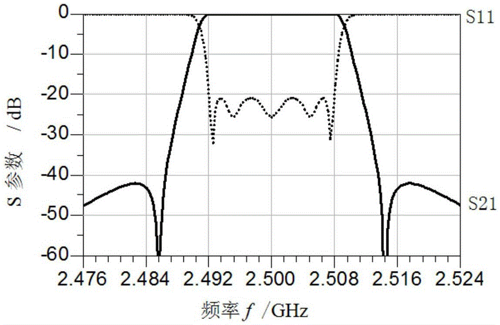
[0027] Such as Figure 1-Figure 9 Shown are various forms of preferred embodiments of the invention and their frequency responses.

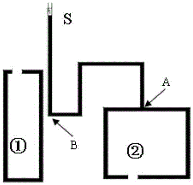
[0028] Preferred embodiment: the filter of the present embodiment includes the filter main channel that is made up of resonator 3,4,5 and resonator 6, and described filter also includes the energy absorption coupling that inserts input, output end with additional coupling mode The energy absorption coupling unit is composed of two resonator 1 and resonator 2 with the same or similar frequency and energy coupling. As a further preferred solution, the resonant frequencies of the two resonators in the energy absorbing coupling unit may be equal to the center frequency of the filter, or may be different values. Make the resonant frequency of the two resonators of the energy absorbing coupling unit equal to the cent...


PUM


Abstract

The invention provides a filter, which comprises a main path of the filter and an energy absorbing and coupling unit, wherein the energy absorbing and coupling unit is connected to an input end and an output end in an additional coupling manner; and the energy absorbing and coupling unit comprises two resonators which are the same or similar in frequency and have couplings. The filter provided by the invention can directly generate a pair (two) of transmission zero points through first-order additional coupling, or even generate multiple pairs of transmission zero points, so that the physical size of the filter can be greatly reduced; and meanwhile, the key problem that the filter does not have a cross coupling, but can achieve the transmission zero points of the filter is also solved. Asymmetrical distribution of the transmission zero points can also be achieved by properly adjusting the frequencies of various resonators in the energy absorbing and coupling unit; and the problem of random distribution of the transmission zero points is solved. Meanwhile, the filter provided by the invention does not have limitation on the resonator structure, so that all resonators can adopt the same shape, do not need to introduce a coupling intersection line; and the whole design process is like the design process of a traditional chebyshev filter and becomes relatively simple.

Description

technical field [0001] The invention relates to the technical field of filter devices, in particular to a design of a filter without cross-coupling but with a transmission zero point and a method for adjusting the transmission zero point of the filter. Background technique [0002] Strong anti-jamming capability has become one of the most important performances of contemporary communication systems. In wireless communication systems, interference mainly comes from electromagnetic waves with frequencies close to the passband frequency, especially adjacent frequency signals. Interference will lead to the reduction of the coverage of the communication base station, a sharp drop in communication capacity, and a sharp drop in signal quality. When the interference is severe, it may even cause the communication system to be paralyzed. For the new generation of digital communication systems, the negative effects of various interferences will be more serious, mainly because high-spe...

Claims


Application Information

Patent Timeline
IPC IPC(8): H01P1/20
CPCH01P1/20
Inventor 张天良羊恺罗显虎华克钊党伟文伟田明恩
Owner UNIV OF ELECTRONICS SCI & TECH OF CHINA
Learn More