Eureka AIR delivers breakthrough ideas for toughest innovation challenges, trusted by R&D personnel around the world.

High-power nanosecond and picosecond pulse fiber laser system

A technology of fiber lasers and picosecond pulses, applied in the field of optoelectronics, can solve problems such as power fluctuations, difficulty in adjusting pulse shapes, and limiting laser peak power, so as to improve operability and safety, improve reliability and stability, The effect of suppressing nonlinear effects

Inactive Publication Date: 2016-06-15
WUHAN RAYCUS FIBER LASER TECHNOLOGY CO LTD
View PDF7 Cites 11 Cited by
  • Summary
  • Abstract
  • Description
  • Claims
  • Application Information

AI Technical Summary

Problems solved by technology

Although short-pulse lasers can be obtained by driving semiconductor lasers with short pulses, the pulse width is relatively narrow. If not processed, the pulse will be broadened and the noise will be enhanced during re-amplification, which limits the increase in the peak power of the laser.
At the same time, the pulse shape is difficult to adjust, and the ability to resist feedback light is poor
[0004] During the long-term use of the laser, the power of the pump semiconductor laser and other devices will fluctuate due to the influence of temperature, which directly affects the stability of the output power of the laser. The consistency and integrity of the laser processing process cannot meet the requirements.

Method used


Image

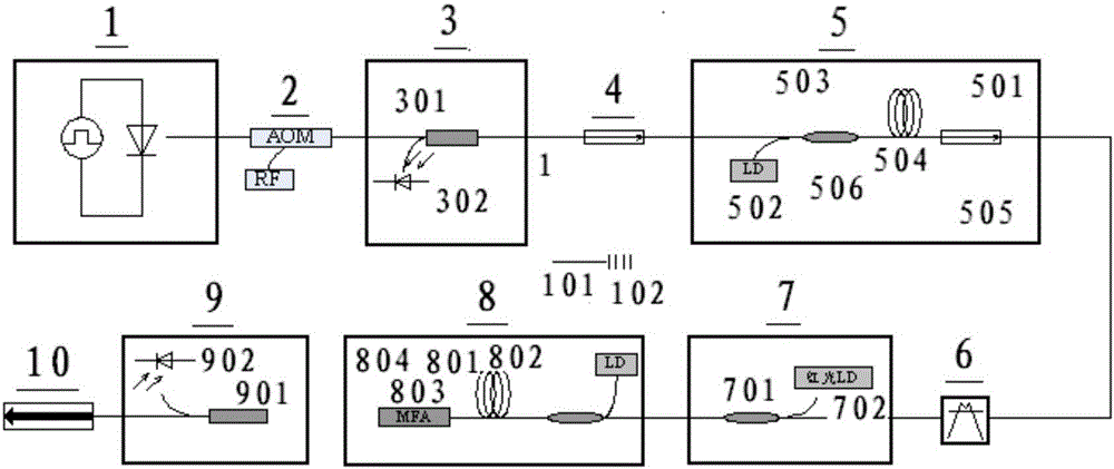
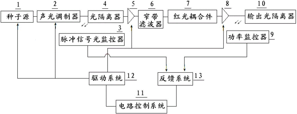
  • High-power nanosecond and picosecond pulse fiber laser system
  • High-power nanosecond and picosecond pulse fiber laser system

Examples


Embodiment Construction

[0022] Embodiments of the present invention are described in detail below, examples of which are shown in the drawings, wherein the same or similar reference numerals designate the same or similar elements or elements having the same or similar functions throughout. The embodiments described below with reference to the accompanying drawings are exemplary, and are only used to explain the technical solution of the present invention, and should not be construed as limiting the present invention.

[0023] In the description of the present invention, the orientation or positional relationship indicated by the terms "inner", "outer", "longitudinal", "transverse", "upper", "lower", "top", "bottom" etc. are based on the drawings The orientations or positional relationships shown are only for the convenience of describing the invention and do not require the invention to be constructed and operated in a specific orientation, and thus should not be construed as limiting the invention. ...


PUM


Abstract

The invention relates to the technical field of photoelectricity, and provides a high-power nanosecond and picosecond pulse fiber laser system. The high-power nanosecond and picosecond pulse fiber laser system comprises a control circuit system, a drive system, a feedback system, a seed source, an acousto-optic modulator, a pre-amplifier stage, a primary amplifier stage, a pulse signal optical monitor and a power monitor, wherein the control circuit system is connected with the drive system and the feedback system respectively; the seed source, the acousto-optic modulator, the pre-amplifier stage and the primary amplifier stage are connected with the drive system and are controlled by the drive system; the pulse signal optical monitor and the power monitor are connected with the feedback system and transmit signals to the feedback system; the drive system drives the seed source to become pulse signal laser lights through the acousto-optic modulator; a small amount of pulse signal laser lights are transmitted to the pulse signal optical monitor; a large amount of pulse signal laser lights are transmitted to the primary amplifier stage through an optical isolator and the pre-amplifier stage and are output from the optical isolator; meanwhile, a small amount of lights are transmitted to the power monitor; the pulse signal optical monitor and the power monitor transmit the collected signals to the feedback system; and the collected signals are fed back to the control circuit system by the feedback system. Therefore, the technical problems of high-power nanosecond and picosecond pulses are solved; and good effects of high transmission rate and stable signal are achieved.

Description

technical field [0001] The invention relates to the field of photoelectric technology, in particular to providing a high-power nanosecond and picosecond pulse fiber laser system. Background technique [0002] High-power nanosecond and picosecond pulsed fiber lasers have the advantages of good beam quality, narrow pulse width, "cold" burning of materials, high reliability, easy integration and no need for complicated maintenance, etc., and have been more and more popular in the market Attention, especially in the field of micro-scale materials processing. [0003] In the prior art, the nanosecond and picosecond pulses with high peak power are mainly obtained by the main control oscillation-amplification (MOPA) method, and the seed source MO generally uses a modulated semiconductor laser with a fast response speed to generate a pulse width of nanoseconds, Picosecond-level seed light, the seed light is injected into the amplifier PA for amplification. Although short-pulse las...

Claims


Application Information

Patent Timeline
IPC IPC(8): H01S3/11H01S3/067H01S3/117H01S3/10
CPCH01S3/11H01S3/06754H01S3/10015H01S3/117
Inventor 李科
Owner WUHAN RAYCUS FIBER LASER TECHNOLOGY CO LTD
Why Eureka
Eureka Blog
Learn More