
Dynamic simulation system applying two-stage DC voltage for hybrid DC power grid

A technology of DC voltage and hybrid DC, applied in the direction of AC network circuits, power transmission AC networks, circuit devices, etc., can solve the problem of not being able to combine dispatching control and relay protection, not being able to analyze the dynamic response characteristics of system parameters, and not considering the network Issues such as architecture monitoring and scheduling, to achieve the effect of a good test environment

Inactive Publication Date: 2016-06-15
ELECTRIC POWER RESEARCH INSTITUTE OF STATE GRID SHANDONG ELECTRIC POWER COMPANY +1
View PDF1 Cites 9 Cited by
  • Summary
  • Abstract
  • Description
  • Claims
  • Application Information

AI Technical Summary

Problems solved by technology

[0003] The existing simulation system for the power grid can only realize the simulation of the network architecture, without considering the monitoring and scheduling of the network architecture, and cannot combine the functions of dispatch control and relay protection with the network architecture, so , and it is impossible to analyze the dynamic response characteristics of system parameters

Method used


Image

  • Dynamic simulation system applying two-stage DC voltage for hybrid DC power grid
  • Dynamic simulation system applying two-stage DC voltage for hybrid DC power grid
  • Dynamic simulation system applying two-stage DC voltage for hybrid DC power grid

Examples


Embodiment Construction

[0044] The present invention is described in detail below in conjunction with accompanying drawing:

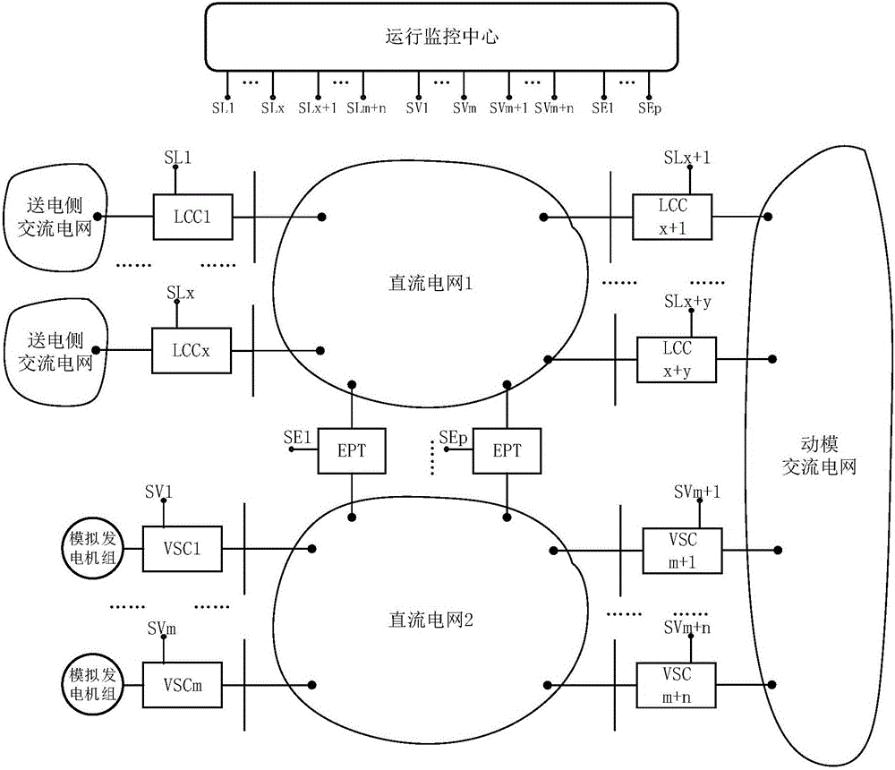
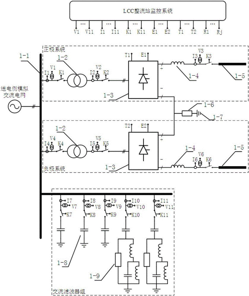
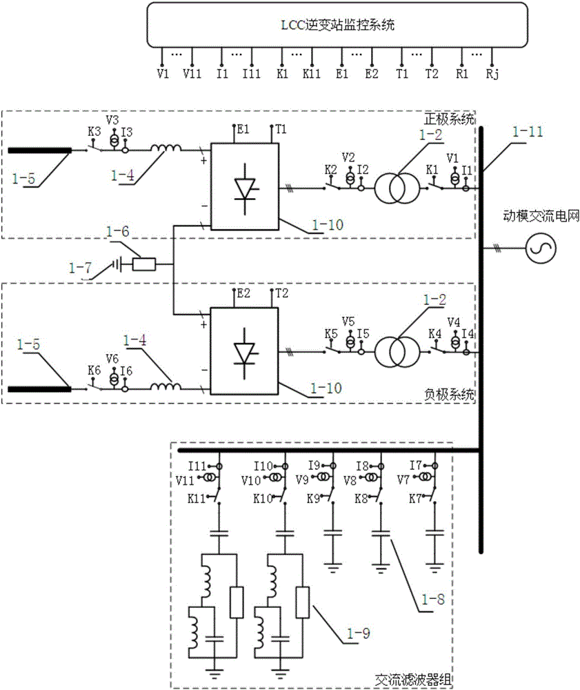
[0045] The invention discloses a hybrid DC power grid dynamic simulation system using dual-stage DC voltage, such as figure 1 As shown, including the operation monitoring center, the converter station based on the current source converter (LCC), the converter station based on the voltage source converter (VSC), the DC power electronic transformer (EPT), the simulated generator set, DC power grid, power transmission side AC power grid, dynamic model AC power grid.

[0046] Among them, LCC rectification converter stations 1~x are connected to the AC power grid on the power transmission side, VSC converter stations 1~m on the generator side are connected to the simulated generator set, LCC inverter stations x+1~x+y are connected to the dynamic The grid-side VSC converter stations m+1~m+n are connected to the dynamic-mode AC grid, and the DC EPT is connected to the two-layer DC g...


PUM


Abstract

The invention discloses a dynamic simulation system applying two-stage DC voltage for a hybrid DC power grid. The dynamic simulation system comprises a converter station based on a current source type converter and a converter station based on a voltage source type converter (VSC), wherein the converter station based on the current source type converter comprises a rectification converter station and an inversion converter station, one end of the rectification converter station is connected with a power transmission side AC power grid, the other end of the rectification converter station is connected with a DC power grid, one end of the inversion converter station is connected with the DC power grid, the other end of the inversion converter station is connected with a dynamic simulation AC power grid, the converter station based on the VSC comprises a power generator side VSC converter station and a network-side VSC converter station, one end of the power generator side VSC converter station is connected with a simulation power generation set, the other end of the power generator side VSC converter station is connected with the DC power grid, one end of the network-side VSC converter station is connected with the DC power grid, and the other end of the network-side VSC converter station is connected with the dynamic simulation AC power grid. By the dynamic simulation system, a reliable and convenient research platform is provided for a system construction scheme of the DC power grid, the design of a dispatching system, research on a control protection strategy and analysis on the dynamic response characteristic, and a favorable test environment is provided for developing and debugging of system engineering.

Description

technical field [0001] The invention relates to the electrical field, in particular to a dynamic simulation system for a hybrid direct current power grid using dual-level direct current voltages. Background technique [0002] With the development and improvement of high-voltage direct current transmission technology, the number of high-voltage direct current transmission projects based on current source converters and voltage source converters has gradually increased, forming multiple direct current transmission lines with different transmission types, voltages, capacities and landing points. The transmission mode in which lines coexist in the same grid forms the prototype of a hybrid DC grid. In order to realize the construction of the Energy Internet, it is necessary to conduct detailed research on the network architecture, dispatch control and relay protection of the hybrid DC power grid. [0003] The existing simulation system for the power grid can only realize the sim...

Claims


Application Information

Patent Timeline
Patent Type & Authority Applications(China)
IPC IPC(8): H02J3/36
CPCH02J3/36H02J2203/20Y02E60/60
Inventor 任敬国郑建陈玉峰姚金霞辜超李秀卫袁海燕王辉李杰王斌马艳杨祎彭飞王建朱庆东白德盟师伟张振军
Owner ELECTRIC POWER RESEARCH INSTITUTE OF STATE GRID SHANDONG ELECTRIC POWER COMPANY
Learn More